Does calibration for antenna orientations exist?
I have two DWM1000 module and depending on how they are oriented to each other, I get different range measurements. Has there been research done on this problem?
Does calibration for antenna orientations exist?
I have two DWM1000 module and depending on how they are oriented to each other, I get different range measurements. Has there been research done on this problem?
It’s a known issue.
But unless you know the orientations of both antennas there is no simple way to correct for it.
Getting the module and it’s antenna away from any other metal/pcb helps but ultimately if this is an issue for you the best solution is to use a different antenna.
Assuming I know the orientations of the anchor modules and from measurements, I also know the orientation of the tag. How would you correct for orientation? Doing multiple calibration on different orientations?
The only sure way would be to have a big lookup table with all antenna angle permutations.
You would need to measure the data for this table.
You’d also need to check whether the effect in the table is constant or whether it’s signal power dependent and if so what that function was.
When testing I did notice that you get some fairly large discontinuities in the range at some angles, most of the time it was fairly nicely behaved but then I would get a of 15cm over very small angle changes.
Personally I took the easy way out and changed the antenna.
Thanks a lot, currently I am using the antenna which came with the DWM1000 module? Any recommendation for antennas which are more omnidirectional?
Depends on how good you want it. A PCB antenna on the end of an SMA cable is a lot better but still not perfect. The only completely symmetrical ones we could find were stupidly expensive so we ended up building our own.
As AndyA pointed out it is a known issue. Indeed, taking a good antenna helps a lot, however, in a 3D setup you most certainly have some non-omnidirectional effects influencing your range measurement. By fusing multiple range measurements (with inertial measurement unit/odometry/ground truth data) you can come up with a lookup table as also pointed out by AndyA. Instead of using a lookup table, it’s also possible to use a machine learning algorithm as for example done here: https://ieeexplore.ieee.org/stamp/stamp.jsp?tp=&arnumber=8561287
Instead of using a lookup table, it’s also possible to use a machine learning algorithm as for example done here: https://ieeexplore.ieee.org/stamp/stamp.jsp?tp=&arnumber=8561287
Or one other option is to significantly over determine the position by using lots of range measurements. While this doesn’t remove the errors it does tend to average them out and so reduce their impact.
@legatus Hi thanks for the mention, in fact I studied his paper and it turns out to be exactly what I need. Although he only conducted the experiment for yaw angles, I would also consider taking roll and pitch angles into consideration (not all 360 degree since I am using a drone as well). In practice, the drone will move whereas there are roll/pitch/yaw movements at the same time. Am I right to assume that if I know the offset (and its variance/certainty) for a specific orientation, I can interpolate the final offset from the single yaw/pitch/roll offset?
Probably going to use my VICON system for ground truth data instead of going for IMU fusion like he does.
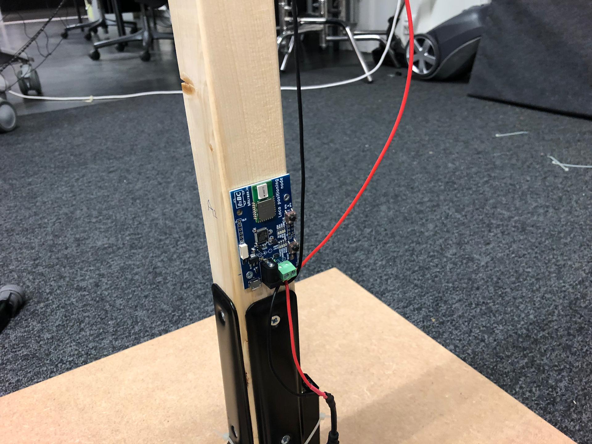
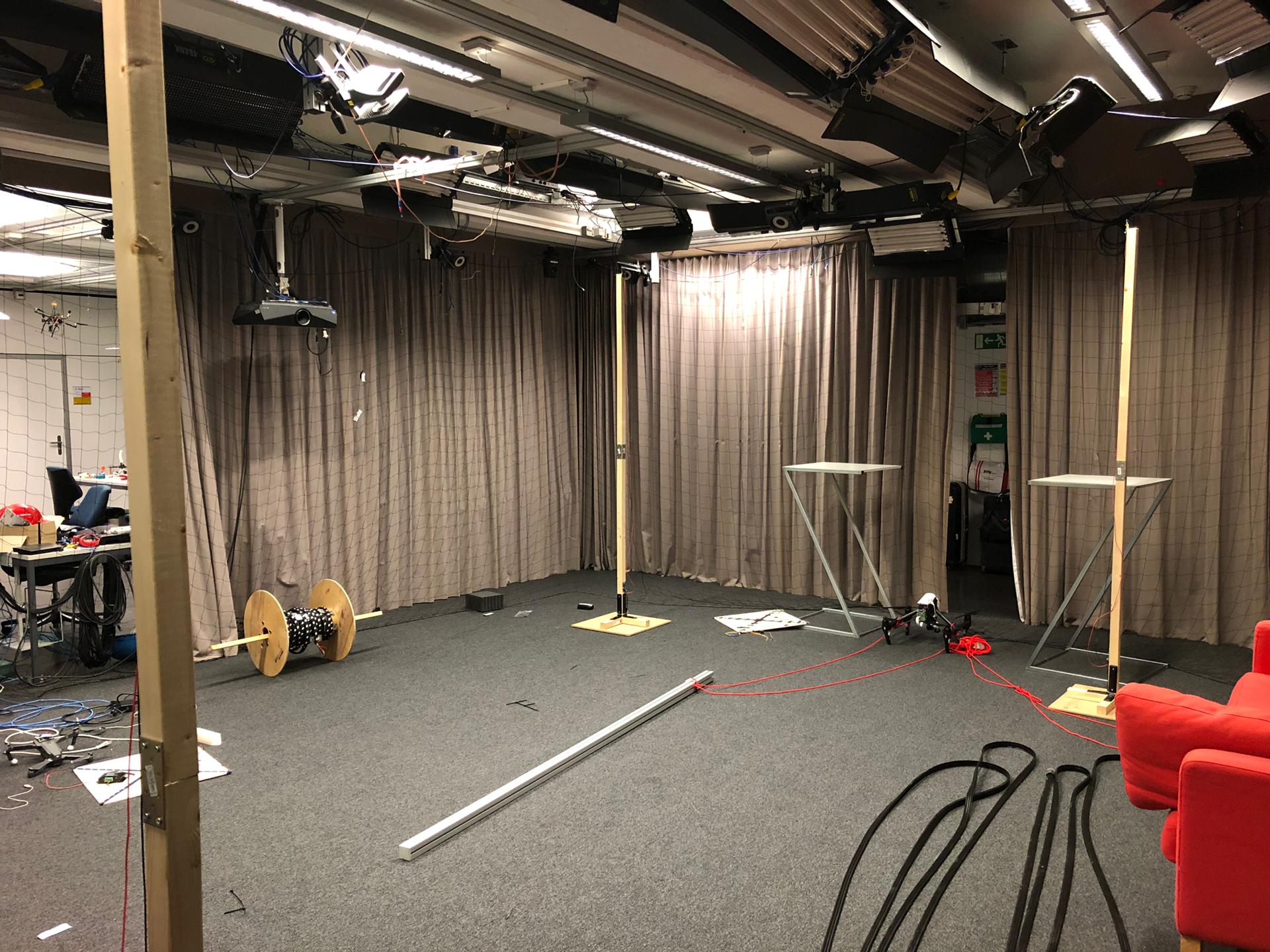
@AndyA Thanks for your last input, right now Im aready using 8 anchors as can be seen on the picture, I dont think I can go any further with anchor number ![]()
What I essentially doing is using Gauss-Newton to determine the tag position.
This depends on grid spacing/lookup table from which you do the interpolation and the variation your system has over different orientation. As long as your interpolation point is close enough (given the variation in your system) to the grid points/lookup table, it should work.