Hi guys,
I’m reading the DWM1001_Datasheet document and I’m trying to understand the meaning of the following Table (11 inside the document)
[attachment=188]
Now please consider the first sub picture, the blue one (XZ plane).
The fixed antenna on the center is vertically placed and moreover I have another vertically placed antenna (I suppose) which can be moved according theta and phi angles.
Does theta relate to X axis? And phi on Z?
It is actually not very clear for me…
Now consider the second sub picture, the green one (XY plane).
The fixed antenna on the center is with its “back” on the ground… and what about the second antenna?
Does it is in the same “back on the ground” condition or something else?
Please give me any hint in order to better understand the meaning of these images
In the pictures imagine that the board in the centre is rotating about the axis of the circle. There is then a fixed antenna at the point where Phi and Theta are shown.
So for the first set it rotates such that the antenna remains at the top the whole time. After it has rotated 90 degrees the antenna is on the module is furthest away from the measurement point.
I find it easier to view it this way rather than the measurement point rotating about the board, partly because that’s the way the test is actually done and partly because it avoids confusion as to whether the Theta axis rotates or not as it moves.
The Phi and Theta traces are for exactly the same physical rotation. The are for different antenna polarizations, Phi being vertical and Theta horizontal.
So with the board sitting up as shown in the first diagram and a vertically polarized antenna you will get from around -2 to -5 dB of antenna gain depending on the angle of the board. A variability of 2 or 3 dB is about as close to uniform as you can get. If maintaining that orientation you were to move the antenna up and down you would get good signal until about 40 degrees above or 20 degrees below before the strength then starts to drop off rapidly, that’s based on the theta chart for the YZ plane.
If however you were to mount the board as shown in the first picture and your antenna horizontally you get a 15 dB variation in gain depending on which side you are standing on. Very roughly 6 dB represents a doubling/halving of range so that 15 dB means only getting around 1/4 of the range in some directions.
Thanks for the answer, but I didn’t understand very well to be honest.
As you said, I have an antenna on the center of the plot (now we consider the XZ plane) that rotates along the X and Z axes.
I made two figures…
I have an antenna on the ground which is placed at the origin of the three axes, vertically upright placed.
Now I’m moving another antenna at an altitude h above the ground, which is still vertically placed but in reverse side (the “smile” is reversed).
Moreover, I can have two different scenarios: the antenna on the sky moves toward the up-right and you can see the smile (first group), or it moves toward down-left without seeing the smile (second group).
So in practice, the antenna on the ground is fixed and I have an antenna on the sky which is vertical but rotated by 180 along the z axis.
And the two scenarios imply 0 and 180 degrees along the y axis respectively.
You have offsets in multiple directions at the same time so you’ll have to do a little bit of interpolation. If you were directly above the unit then the YZ Theta chart would be the one to use with directly overhead being an angle of 270 degrees.
Given how symmetrical the XZ Phi chart is I wouldn’t expect a small offset to the side to make much difference to what you see. If you get a long distance to the side this will change.
And since XZ Phi 0 and 180 are virtually the same I wouldn’t expect to see much difference between your two rotations.
Don’t forget that when calculating the overall effect you need to add the two gains together, given your system is fairly symmetrical simply doubling the value from the chart will be close enough.
And ultimately don’t put too much faith in these charts, the ground will have a significant impact on the pattern of the unit on the ground. And every wire, circuit board and battery attached to the system will also have an impact on the antenna patterns. Antenna pattern charts are a good starting point but the only way to be sure of final system performance is to test the final system.
For the benefit of others reading this thread, just to emphasise that you need to use Figure 3 as a reference to the labelling of the planes shown in Table 11.
Also, the radiation patterns were measured using a special horn measuring antenna, rather than with a ‘second’ DWM1001-Dev board, as you suggested, bettisfr.
When you have your product certified in a test lab, they rotate the product on a turntable with the measuring horn antenna oriented vertically (phi polarisation) and also with it oriented horizontally (theta polariasation) in order to find the maximum power. This is what’s presented in the datasheet - though it’s always challenging to present clearly!
Bettisfr,
It looks like an unusual application you have due to the way your nodes move relative to eachother. I would usually suggest trying to keep ranging devices facing eachother (in eachother’s azimuth, or XZ, planes) if at all possible, as this is how you maintain maximum omnidirectionality and location accuracy (as changes in gain lead to variation in ranging results). Are you implementing a TWR system with multiple anchors, or just ranging to a single node?
Now I’m only sending many string messages between a mobile antenna attached to a drone and a fixed antenna on the ground.
This is the first step.
The second step, is to range the node in the same way, that is, fixing an antenna on the ground and using a mobile flying antenna.
Orient the device in order to maintain omnidirectionality. Isn’t the whole point of something being omnidirectional that it the orientation doesn’t matter?
I know what you mean, it’s normal for omnidirectional antennas to only be omnidirectional in a single plane, but the choice of wording made me smile.
If possible, I think it would be good to have more than one fixed antenna on the ground and average the range results so that a less accurate range result when you’re in a null of one antenna can be compensated by a more accurate result from the other antenna.
Yes but by design, I will have one or more fixed antennas on the ground and one mobile flying antenna on the sky.
I will take distance measurements sufficiently apart from each antenna.
Finally I will apply trilateration for estimating the position of each antenna on the ground.
This is a strange application, I know… but it is research
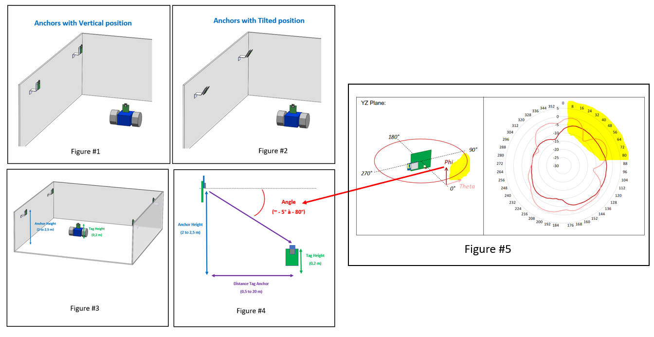
I have some questions about antenna radiation patterns. I tried to understand the table 11 of the DWM1001 datasheet, in the aim to positioning as the best as possible my anchors.
My first idea (without looking at Table 11) was to think that maybe it would be better to tilt the anchors towards the tag (Figure #1 & #2).
But when I look at the XZ plane diagram, and do a little trigonometry calculation (Figure #4) to determine the anchors’angle of view of the tag in the most of the time. I find 5° to 80°, corresponding to 5° to 80° in the XZ plane diagrams.
The antenna gain is correct in this area (figure #5), so I think it is no necessary to tilted the anchors, the vertical position it is pretty good for my application.
Can you tell me if my approach and reading of the antenna patterns diagrams is correct ?