Hi,
I’m currently investigating the clock drift during single-sided two-way ranging with two dw1000.
The manual proposes two different methods to compensate the clock-offset between receiver and transmitter:
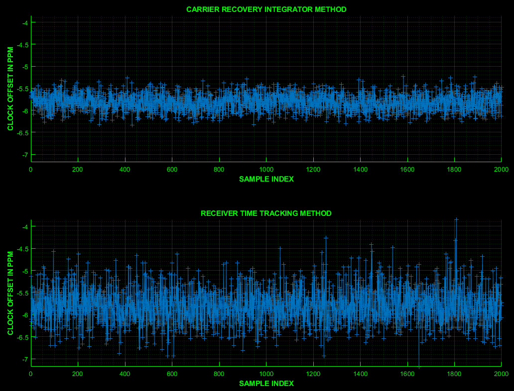
Carrier Recovery Integrator (see page 148, UserManual Version 2.14)
Receiver Time Tracking (see page 99, UserManual Version 2.14)
My observations indicate that both methods give a good estimation of the clock-offset. However the first method seems to be a little bit better.
Now my question: Does anybody know how the dw1000 estimates the clock-offset? Why is there a difference between both estimations?
Thanks in advance
Edit:
I think i found the answer. The Carrier Recovery Integrator seems to be a result of the coherent analysis. The receiver time tracking seems to be a estimation based on the technique also suggested by the IEEE 802.15.4 standard. The values of the Carrier Recovery Integrator works better for me.
How did you reach the conclusion that the method based on the carrier recovery integrator value is more precise than the receiver time tracking offset method ? I am interested because I need to decide which one to use.
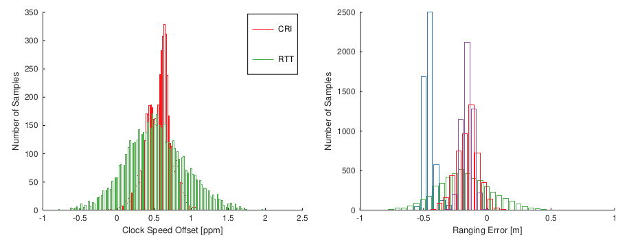
On the left side you see the distribution of the correction values. Green is the Receiver Time Tracking, red the Carrier Recovery Integrator. On the right side you see the according ranging error. Again, red is with CRI correction, green is with RTT correction. Blue is the uncorrected ranging and for cyan I applied a EWMA filter upon the CRI value to reduce the noise of the CRI value.
Blockquote
Correct me please if I am wrong, but if color blue represents the uncorrected ranging measurements in your chart then would this not mean that applying CRI correction results in a decrease in precision and an increase in accuracy ? It looks like the blue measurements are much more concentrated.
Yes, indeed that seems to be the case. Therefore I used an exponentially weighted moving average of the CRI value to reduce its noise.
However, there is a dependency between the response delay and the precision and accuracy of the ranging. If your delay is sufficiently low a uncorrected ranging will perform better than a corrected one. However, for larger delays or for a high clock speed offset you will need a correction method.
PS: I’ve written my thesis about this topic and have done some further measurements. If you are interested I can send you a copy.
The used crystal had a 10ppm accuracy. However, you can use the crystal trim feature (register: FS_XTALT) of the DW1000 to perform a calibration. Thereby you may reduce the clock speed offset below ~0.8ppm. The rest may be corrected via the CRI or RTT values.
Please let me know the Carrier Recovery integrator (Cint) in the following equation is in decimal?
F_offset=(Cint*2^(-17))/2(N_sample/Fs)
why 2^(-17) is used in the above equation?
See UM , 7.2.40.11 Sub-Register 0x27:28 – DRX_CAR_INT
This information is available in the carrier recovery integrator register, at address 0x27, offset 0x28. This is a 21 bit number with the lower 17 bits, the fractional part, and the upper 4 bits as the integer portion of the number.
Leo
Thank you. I mean, I should convert Cint to decimal and insert it into the F_offset equation?
I have used two DW1000, one as a transmitter and other one as a receiver. The transmitter has sent 28 packet and receiver has estimated frequency offset as follows:
[0.0667 0.0673 0.0649 0.0778 0.0754 0.0608 0.0796 0.0652 0.0767 0.0613 0.0795 0.0860 0.0791 0.0737 0.0573 59.4889 0.0729 0.0771 0.0999 0.0933 0.0797 0.0779 0.0963 0.0843 0.0774 0.0930 0.0875 0.0816]
are theses frequency offsets correct? I know the maximum value of frequency offset can be about 59 Hz. why the 15th F_offset is 0.0573 then 16th F_offset is 59.4889?
I’m not sure how you get these figures or what procure you follow. For trimming we have example code sending continues waves to trim the crystal, example 4a.
for the TRIM procedure itself see IC user manual section 8.1.