Hello @mschuh, I forgot to attach my email address last time. Could you please send me a copy of your paper?
Moreover, the clock drift I calculated using CRI looks a little strange compared with @FIRSTDRAGON
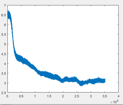
initiator side
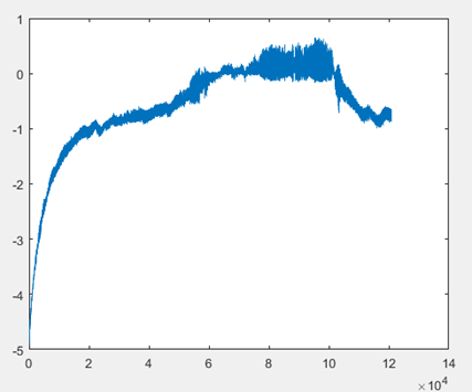
Response side after no interval switchover
( The X-axis is the number of samples, and the Y-axis is in PPM)
What was the temperature doing at the time?
It looks like you started logging at power up which is why there is a rapid change initially.
If this is a circuit sitting out on a desk then changes in airflow in the room could impact it. Put everything inside an insulated box or some other method to isolate it from external influences and let it run for a while before you start logging and you’ll probably get a far more stable trace.
If you have anti-static bubble wrap around then putting some of that around the board is a simple way to buffer it from changes in the room. Don’t use normal bubble wrap.
[mschuh] I also struggle about this topic. May I get a copy of your thesis?
Thank you.
You are right.