Hi everybody,
I have 4 DWM1001-DEV, I configured 1 as a tag and the three others as anchors (1 Tag + 3 Anchors) and I measured the current of the 4 DWM1001-DEV at the same time. (you can see the picture attached)
However, I don’t understand the signification of the peaks… For example, the first peak of the tag could be the poll, and after the 3 RX of Anchor1, Anchor2 & Anchor3. And what is the last peak ?
Moreover, I don’t understand the current consumption of the anchor.
Could someone have the explanation and could explain to me, please ?
Thank you so much,
Hugo.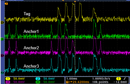
Hi Hugo,
It looks like you are using the default firmware on DWM1001, PANS.
This firmware has a fairly complex network layer, and it involves much more than a basic single sided two way ranging.
For the taf you are right, you can see the TX followed by 3 RX. Please note there could potentially be a 4th RX if you had 4 anchors.
Following that, the tag does an additional Tx for what we call “IoT” data. This can be used to send data to a bridge node for example.
The anchors are very actives when running PANS because they must be synchronized in between each other in order to preserve the correct functionality of the network. For example there is a beacon phase at the star of the superframe for which all anchor will listen to each other. They are not designed for low power application and are supposed to be powered by main.
Hope it helps,
Thanks
Yves
Hi Yves,
Yes, it is the default firmware PANS which is used.
Ok, so the last peak of the tag is not the final TX?
And for the anchors I don’t really understand what is the beacon phase?
So, with the PANS, anchors are not synchronized, isn’t it?
Thank you so much for your quick answer,
Hugo.
Hi Hugo,
On the tag, It is an extra Tx but not related with the calculation of the position. The tag is able to calculate its position after receiving at least from 3 anchors. The extra Tx is required to send IoT data to the bridge node.
The anchors are synchronized over UWB, this requires some additional Tx and Rx. These are what you see on the power analyzer.
Have a look at the system overview documents, and you will see how the superframe is built. That will give some indication regarding the different Tx/Rx you can expect for each nodes within the network.
Thanks
Yves
Hi Yves,
Ok, thank you.
Are these documents available on the Decawave’s website?
Thank you so much,
Hugo.
Hi Hugo,
Yes you can find them on the website:
https://www.decawave.com/dwm1001/systemoverview/
Please note that this document is key and was mentioned multiple times on the forum so maybe check with the research tool next time.
Thank you,
Yves
1 Like
Ok, thank you so much Yves,
Hugo.