Hi ,i am using the DWM1000 and im struggling with read/write a long indexed spi message to configure the LDE_CTRL sub register LDE_CFG1 to change the NTM value to 0x07 (NLOS operation).
im writing and reading from the dwm1000 using an stm32 discovery board and a program in c.
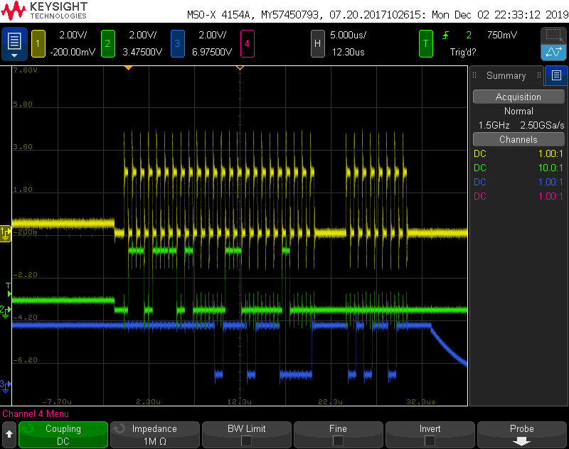
i’ve added photos taken from an oscilloscope of the CLK(yellow line number 1),MOSI(green line number 2),MISO(blue line number 3) of the Read operation to the register(i can only add one photo).
when im reading the register i am recieving (after write and before write) always the value 0xAD ,which is not even the default value 0x3c.
i would very appreciate your help,changing this register value is critical for my mode of operation.
thank you .
Hi,
One of the first tthings to do is to check the SPI functions so that both the reading and writing of DW1000 registers works correctly.
The DW1000 requires that some of the register read and writes are done at SPI rate of < 3 MHz, otherwise rate up to 20 MHz can be used as explained in the DW1000 User Manual and DW1000 Software API Guide.
If a faster SPI rate is used for the low rate reads and writes then the chip will not operates correctly.
And FYI, After DW1000 is powered up, calling an SPI read of register DEV_ID (32-bits) should return 0xDECA0130 if the SPI is operating correctly.
See SPI section in datasheet and APS022 for more information.
Leo
Hi ,thank you for answering.
My spi clock is 1.125 Mhz so the rate is not the problem,moreover my read and write functions with length 2/1 octets long is working fine and I’ve read dev_id and recieved the right value .
My problem only arises when im trying to write/read a register with a 3 octet spi message (long indexed ) than im not recieving the right values ,Altough im transmitting the 3 octets message according to the decawave user manual .
Hi,
The SPI access for extended register offset could be more trickier for 3 octet SPI transaction then it may for 1 or 2.
The tricky part comes from the fact that the MSBit in first (bit6 & bit7) and second octet (bit7) is always significant as it signifies that this is Write if 1 or that there is an extended offset register address or not (as it is with two octet SPI transaction)
So to explain I used the Decaranging software and logged the SPI interaction on reading the register you are asking about.
======================================================================================
Reading extended register offsets
eg: 0x2E sub register 0x0806
Detail from SPI Log
265-Read: [6E8610] EE 44 AD DE
265-Read: [6E8610] EE 44 AD DE
265-Read: [6E8610] EE 44 AD DE
265-Read: [6E8610] EE 44 AD DE
265-Read: [6E8610] EE 44 AD DE
6E -> read register 0x2E with an offset (offset bit set to 1)
86 -> LSByte of register offset with a 1 in the MSBit position to show 2 byte sub address
10 -> MSByte of register offset is 0x0800 but this is shifted right 7 bits so this becomes 10
======================================================================================
Some sample code for this read. I have highlighted the step that may be causing confusion. The code can be found in deca_device.c
{
uint8 header[3] ; // buffer to compose header in
int cnt = 0; // counter for length of header
if (recordNumber > 0x3F) return DWT_ERROR ;                    // record number is limited to 6-bits.

// Write message header selecting READ operation and addresses as appropriate (this is one to three bytes long)

if (index == 0)                                         // for index of 0, no sub-index is required
{
    header[cnt++] = (uint8) recordNumber ;              // bit-7 zero is READ operation, bit-6 zero=NO sub-addressing, bits 5-0 is reg file id
}
else
{
    if (index > 0x7FFF) return DWT_ERROR ;                     // index is limited to 15-bits.
    if ((index + length)> 0x7FFF) return DWT_ERROR ;           // sub-addressible area is limited to 15-bits.

    header[cnt++] = (uint8)(0x40 | recordNumber) ;      // bit-7 zero is READ operation, bit-6 one=sub-address follows, bits 5-0 is reg file id

    if (index <= 127)                                   // for non-zero index < 127, just a single sub-index byte is required
    {
        header[cnt++] = (uint8) index ;                 // bit-7 zero means no extension, bits 6-0 is index.
    }
    else
    {
        header[cnt++] = 0x80 | (uint8)(index) ;           // bit-7 one means extended index, bits 6-0 is low seven bits of index.
        header[cnt++] =  (uint8) (index >> 7) ;           // 8-bit value = high eight bits of index.
    }
}

// do the read from the SPI

return readfromspi(cnt, header, length, buffer);  // result is stored in the buffer
}
so instead of 0x6E 0x86 0x08
you need
0x6E 0x86 0x10
I hope this explains your problem.
Regards
Leo
It worked ! Thank you very much .