Sorry if this was already discussed here but I couldn’t find related posts.
I’m having communication issues between some of my tags and the (single) anchor. Doing some debug, I found that tag transmits but anchor can’t receive it. Anchor is built with DWM1000.
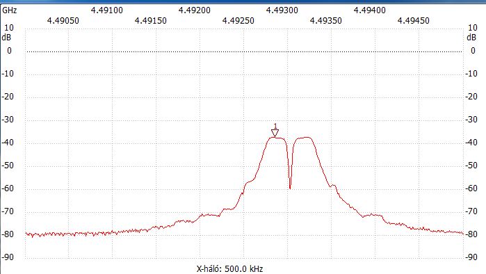
I have custom boards with DW1000 IC for tags. Finally, I got a cheap spectrum analyser and checked frequency based on users manual CW mode suggestion. I captured the plot, however, I’m unsure if this should look like this. I’m using CH3 in this test and put the marker to the expected frequency 4492.8MHz.
It’s not visible on this plot but I can see 2x harmonics at ± 38MHz of the nominal frequency. Is it normal to have an inter modulation with the clock?
I tried to tune the oscillator but not much success.
Some other tags are working fine with the same setup and code.
Do I need to calibrate power and spectrum as well?
I had no issues with DWM1000 modules, hence I think I have some kind of calibration issues.
Also, I’m using my own code, not the library DecaWave provided.
Your graph definitely differs from my one.
I think I’ll do following; I’ll ceck the same test config for one of my tags with DWM1000 and compare.
I will put here the result.
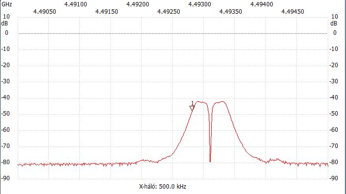
So, the same dip in the middle of band and slightly different center freq compared to my previous post with DW1000 and custom PCB. I put marker to the nominal center which is 4492.8MHz but I can consider this deviation as missing calibration of my spectrum.
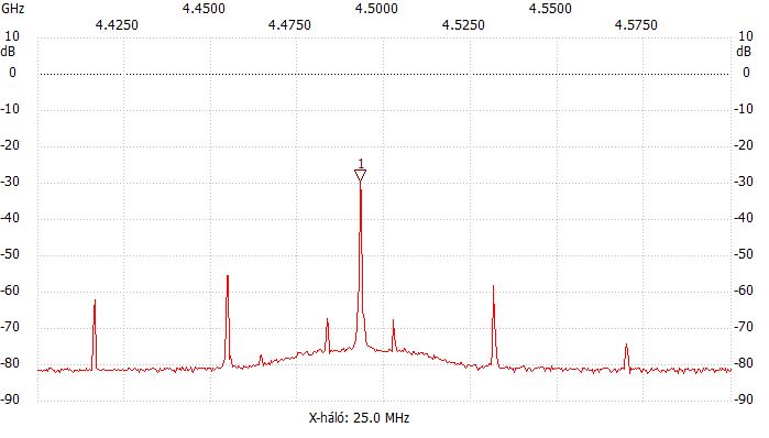
I also took a screenshot with more span, in this one it is 200MHz:
This is still the DWM1000 and I also see the harmonics in ± 38.4MHz which makes me suspicious of intermodulation with clock signal.
I’m unsure if this is what I should see but I can confirm that this DWM1000 tag works perfectly in non-test conditions.
I’m a bit lost…
Do I have measurement errors? Or should anything else configured for test mode than description mentioned in users manual above?
Anyone from DW, do you have guys some reference plots I could compare my one?
What is your measurement setup?
What antenna do you have on the analyser input?
What are the resolution and video bandwidths set to?
That you see a broader spike them I do could be explained by the settings used. But that notch in the middle is very odd.
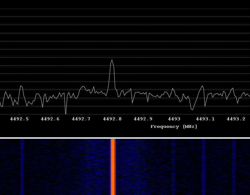
I don’t have a spectrum analyser that can go up to those frequencies so I’m using a HackRF SRD and running an FFT on the data. I have that connected directly to a passive UWB antenna.
My setup is fairly easy and cheap one, hence far from perfect.
I’m using a NWT6000 box (cheap ebay) with WinNWT4 software. Antenna is an omni with SMA connector, made for 5G wifi. DWM1000 is radiating through its ceramic chip antenna, my own board has a PCB antenna designed using HFSS (well, that antenna is designed for CH5 but I can’t get over 6GHz with my measurement setup…).
So no direct RF coupling, tag and spectrum input is around 200mm distance and line of sight with plaster walls within a meter.
With this WinNWT software, there’s no such RBW, VBW or span. Above plots were set up for 500 measurements for the entire bandwidth. The X resolution is on the snippet, top one is 4MHz, bottom one is 200MHz.
I know this is not a lab config but being a one-man project in development phase this is what I can afford now.
However, as of my current knowledge I can’t think of any circumstances which could cause that dip in the middle.
That’s why I would appreciate if DecaWave guys could publish a CW waveform recorded in their lab.
Hey dk1,
Hope you are doing well ! I am working with a decawave TREK1000, in order to detect UWB waves emitting on a 4GHz central frequency. I actually have a USRP, and want to buil a setup to detect the signals in a wirless manner. Do you have any adices or insights, thank you for your help !!
Best,
Bassel
Unfortunately, I can’t give you much advice on TREK as I never used it.
I’m using my own code, with my own developed time division system. I wrote the whole code in PIC assembly (my tag is a 16F18323 and anchor is a 18F45J50). I had to use CW mode to verify my setup and my own tag design using a custom PCB with the PIC and DW1000 IC. Symptom was no or unreliable receiving on anchor end. I believed that I was having issues with frequency, but turned out that my custom board power section was inadequate and not carefully designed. (DC-DC converter, coupling and buffer capacitors)
After reading a lot on the forum, especially Mike Ciholas’ interesting and extremly useful comments, I managed to fix the issues. I’d like to say thanks to Mike in this way…
However, due to covid, I wasn’t able to progress with my little system as I’m doing it as a hobbist.
If your question was more related to the measurement setup, you can have a look up to my previous comments where I described the setup, well, which is more like a “guesser” than a proper measurement setup.
If you’re interested in what code I used for filling up registers to get DW1000 into CW test mode, I can provide it to you, but again, they are just raw data only and nothing to do to TREK.
I hope that others, advanced in TREK could give you an exact answer how to switch to CW mode with it (is there a command for that?)…
Thanks,
Dez
Thank you for your complete answer and help Dez !!
I would be really interested to see your own code for the DW1000 !
To give a clearer idea about my work, I am trying to detect my TREK1000 tags signals to record an IQ data. I am doing this through a Gnu radio companion flowgraph. I have done this process but when the tags are directly linked to the USRP through an SMA cable, which is not the case in a wireless communication.
Thus, I would be really thankfull for any insight Dez,
Thank You for your time and help,
Bassel
Sorry about the delayed reply, I was away recently but now I’m back.
I copied my routine which puts the DW1000 into CW mode after a proper initialisation is done.
As mentioned, it’s written in PIC ASM (PIC16F18323) but you can check and use the register values filled in. CW_Code.txt (2.8 KB)
Just some explanations:
The pic has only 8bit SPI, so all data are in 8bit chunks. Hence I call my SPI routine after each byte. (Yes, this code could have been written using some table mechanism like retlw but this was more easier for me to do troubleshooting. Probably I’ll do that in future…)
One register fill is between the SPI CS off/on macros. So my process is to pull the SPI CS pin on DW100 low, then send the bytes, once completed, I pull the SPI CS up again.
In one register fill, the first byte is always the register address. Please note that writting a register requires the register address bit 7 set. Also, using sub address for a register needs bit 6 set. So, for example, my first register fill is for register 0x28 - RF_Conf, sub-register 0x00 and value is 0x0009A000. Please note that the DW1000 needs data in 4x octetts and coded in little endian, means that basically you transmit the “least significant byte” first. So the full 8bit SPI transmission should look like: 0xE8, 0x00, 0x00, 0xA0, 0x09, 0x00 (How easy to code in high level languages, or just using the pre-made TREK, isn’t it
The code is basically filling up the necessary registers as per DW users manual, using the same structure.
Please note, that provided values are for CH3. Reason behind doing CW test on CH3 is that my spectrum analyser (well, this is a bit flattering for that cheap ebay box I got…) is only capable up to 6GHz, so CH5 is out of my view. However, you can replace register values to use any of the channels, just see the users manual.
You can find the whole process in the DW1000 Users Manual v2.18 page 198.
Hi Dez !
Thank you for your help, your time and this complete answer !!
Since it’s kind of new for me, what app and program are you using to code, and how your software/hardware set up is connected ?
Excuse my biginner questions, it’s my first time dealing with this situation !
And really thank you for your help !!
Best
Bassel
I’m using Microchip MPLABX and a Pickit4 debugger for programming the controller.
I’m using the hardware SPI module to communicate with DW1000. It works well, however, I had to put a low value capacitor (300pF) on one of the data legs, I can’t remember if MOSI or MISO as I’m not in front of my system.
The DW1000 Users Manual is my holy bible, everything is written there I needed so far. A really good documentation for an exceptional device