Hi,
I notice a small error on the EVB1000 schematic. In the schematic LED3 is connected to GPIO2 on the DW1000 and LED4 is connected to GPIO3. In reality, this is the reverse: LED3 -> GPIO3 and LED4 -> GPIO2.
Hi,
I notice a small error on the EVB1000 schematic. In the schematic LED3 is connected to GPIO2 on the DW1000 and LED4 is connected to GPIO3. In reality, this is the reverse: LED3 -> GPIO3 and LED4 -> GPIO2.
Hi Loic
Could you confirm how you came to this conclusion.
The schematic is correct. But if you have compared the schematic with the EVK1000 user manual. then the EVK usermanual is incorrect.
/Leo
Hi DecaLeo,
I think the description of LED3 and LED4 is correct on EVK1000. I have noticed the error on schematic because LED3 was blinking during transmition and LED4 during reception. To confirm that I manually trigger an LED blink by writing in PMSC_LEDC register via the DW1000 device driver API:
// GPIO 4 blinking
uint32_t reg;
reg |= 0x00080000UL;
dwt_write32bitoffsetreg(PMSC_ID, PMSC_LEDC_OFFSET, reg);
reg &= ~0x00080000UL;
dwt_write32bitoffsetreg(PMSC_ID, PMSC_LEDC_OFFSET, reg);
But I didn’t confirm that by a continuity test.
Loïc
Hi
Also check the datasheet for the DW1000.
PIN 36 / GPIO 2 RX LED: (LED3 on PCB)
General purpose I/O pin.
It may be configured for use as a RXLED driving pin that can be used to light a LED during receive mode. Refer to the DW1000 User Manual [2] for details of LED use.
This pin has an internal pulldown to VSSIO and can be left unconnected if not being used.
PIN 35 / GPIO3 TX LED / LED4 on PCB
General purpose I/O pin.
It may be configured for use as a TXLED driving pin that can be used to light a LED following a transmission. Refer to the DW1000 User Manual [2] for details of LED use.
This pin has an internal pulldown to VSSIO and can be left unconnected if not being used.
With the above taken into account this means that LED 4 is TX and LED 3 is RX.
And so EVK User Manual is incorrect.
Regards
/Leo
Hi,
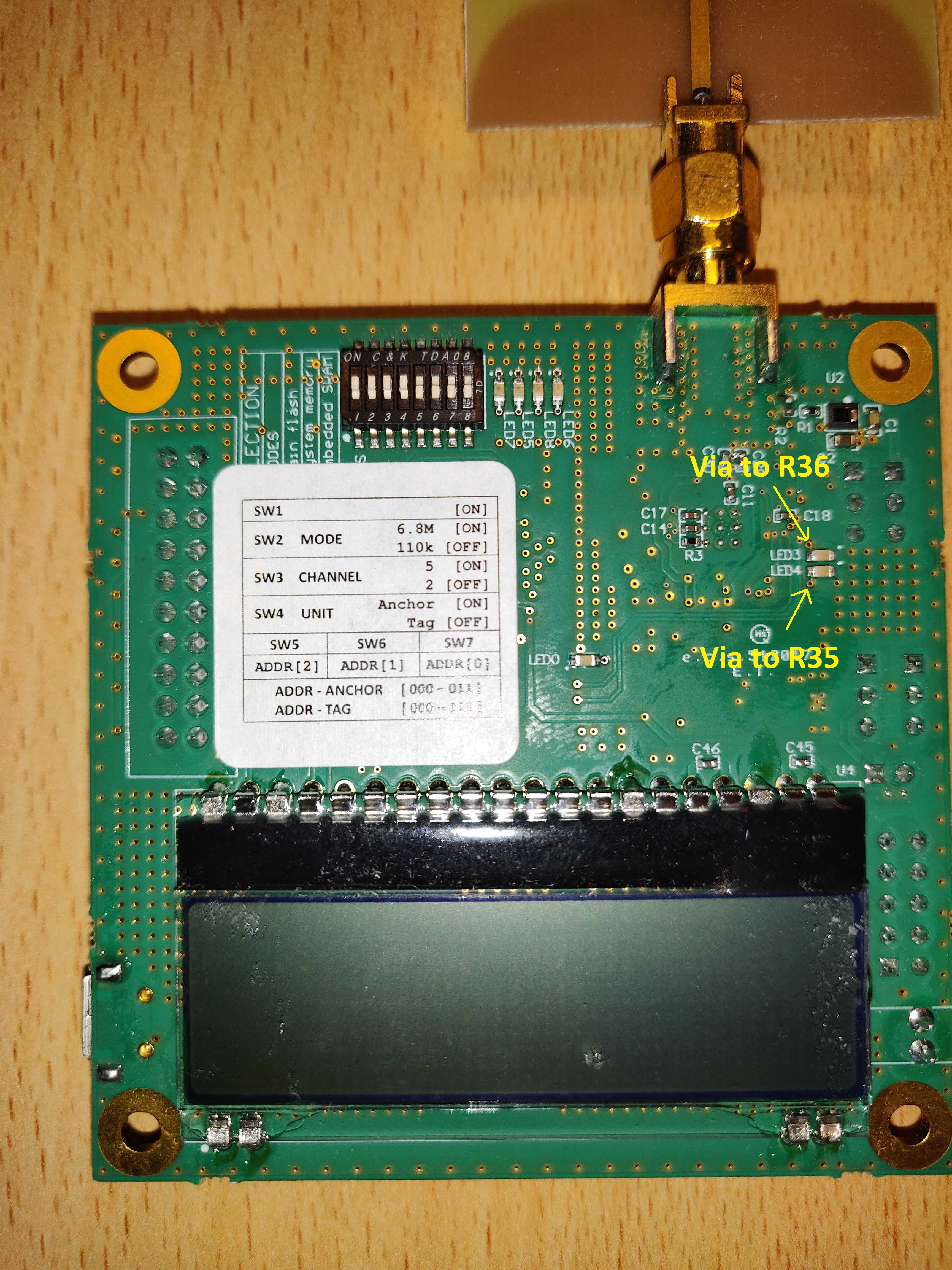
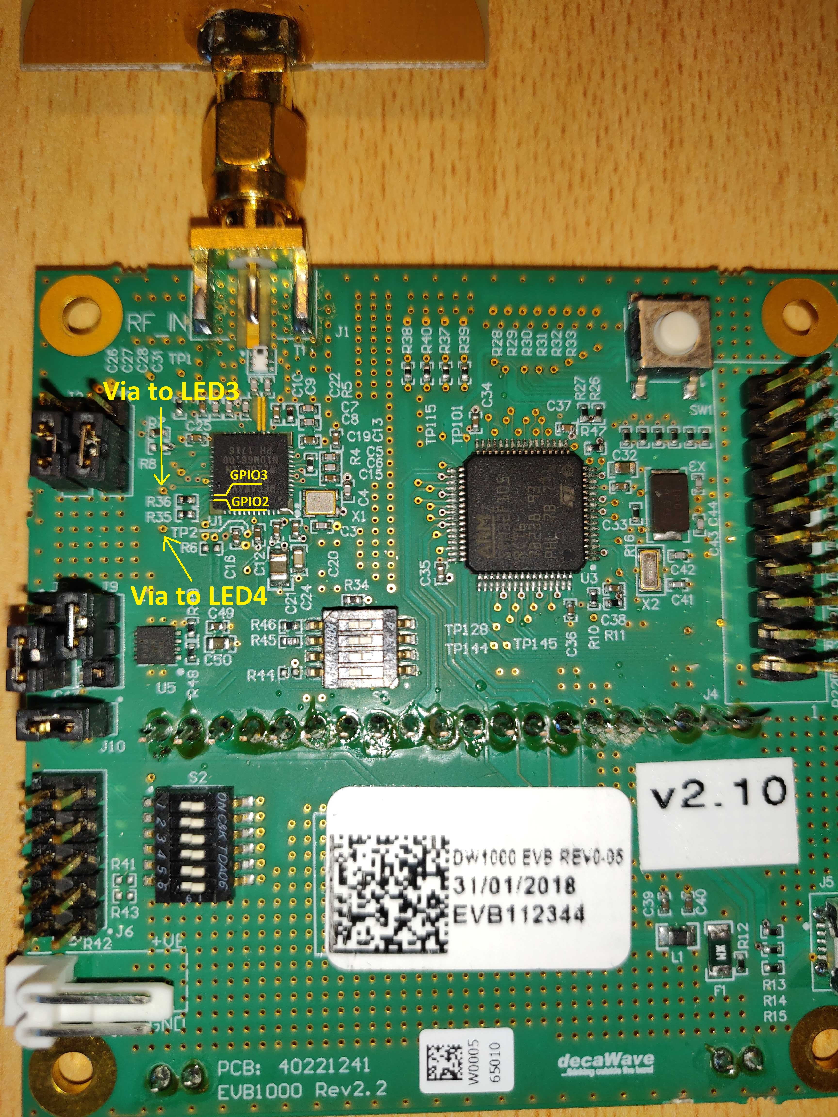
I think you are wrong. I confirm by a continuity test that LED3 is connected to GPIO3/TX LED and LED4 to GPIO2/RX LED on EVB1000 REV0-05.
If you take a look to the bottom side and top side of the PCB, LED4 is connected to R35 and LED3 is connected to R36:
Kind regards,
Loïc
Hi Loic
You’re correct ,
Double checking it seems that the naming for LED3 and LED4 are reverse, so LED3 should in fact be LED4 and LED4 should be LED3
Thanks for pursuing this
/Leo
I am trying to change register 0x26 so the txled and rxled to be as a general output input but I am trying to control them and I am not sure what are the reference pin numbers. In the manual it says GPIO3 and GPIO2 of dw1000 which correspond to p35 and p36? (i am using mbed os)
Could someone explain this?