Suppose the topology bellow exists with 5 x 5 anchors spaced perfectly with 25 meters and operating at 6.8 Mbps. When the tag1 send its position to anchors , how this information is propagated until the gateway ? I know that each anchor has a slot time to send information and only 30 anchors can send at the same time. How an anchor replicates the information that comes from another anchor?
Now suppose that network speed is changed to 110Kbps and the topology and distances are still the same. What happens with the air interface as aloha protocol is used? All anchors and tags have their sensitivity increased. So the point is: will the collisions increase because each anchor covers a wider area ?
I believe you are referring to the PANS RTLS library for DWM1001.
1.The anchors “replicate” some information but that’s only to maintain the network, and it does not contain tag position. Basically, any node (either anchors or tag) must be in direct range with a gateway, there is no relay. You will need several gateway to cover large area, or to overcome obstacles.
PANS is not compatible with a lower update rate, we cannot confirm the scheme would work correctly in such a configuration. There would be reduction of number of tags and anchors available within the network (as frame would be significantly longer, you can fit less of them within the superframe)
Thanks for your answer but could you please detail a little bit more ? I did not understand because according to DWM1001 system overview , item 5 , it explains the network scalability. So you can increase your network using just one gateway. The problem I don´t understand is that if I have a TAG sending a packet to a group of anchors how these anchors replicate tag´s information until the data reaches the gateway.
The way you explained, this never happen and I could never have a network of, let´s say, 10 x 10 anchors.
Could you clarify the answer ?
I think each of you talked about something else when mentioning about the scalability and 30 anchors.
@nudel If I understand correctly what you want to know is if you can place more than 30 anchors. Yes, that is possible if you follow the deployment rules. The idea is in order to reuse the air-time, there must be some area where some of the anchor slot would be free and it would not influence any other anchor if that slot is used by a newly joining anchor. If you place more than 30 anchors into an area where they would be in-range with each other then only 30 anchors will be connected. The rest will be waiting for a free slot, i.e. until some connected anchor dies.
Regarding the gateway placement - there is no data hoping in PANS. The gateway must see the Tags/Anchors in order to provide uplink/downlink data with the server. You need to place enough gateways to cover the whole intended tracking area.
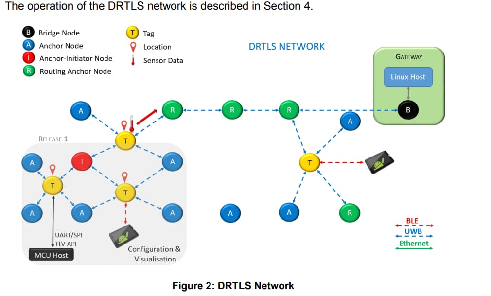
This picture is not up to date, I understand the confusion.
The routing anchors concept was not implemented for performances issues.
Please download the latest documentation from our website, and have a look at the gateway deployment guide as well.
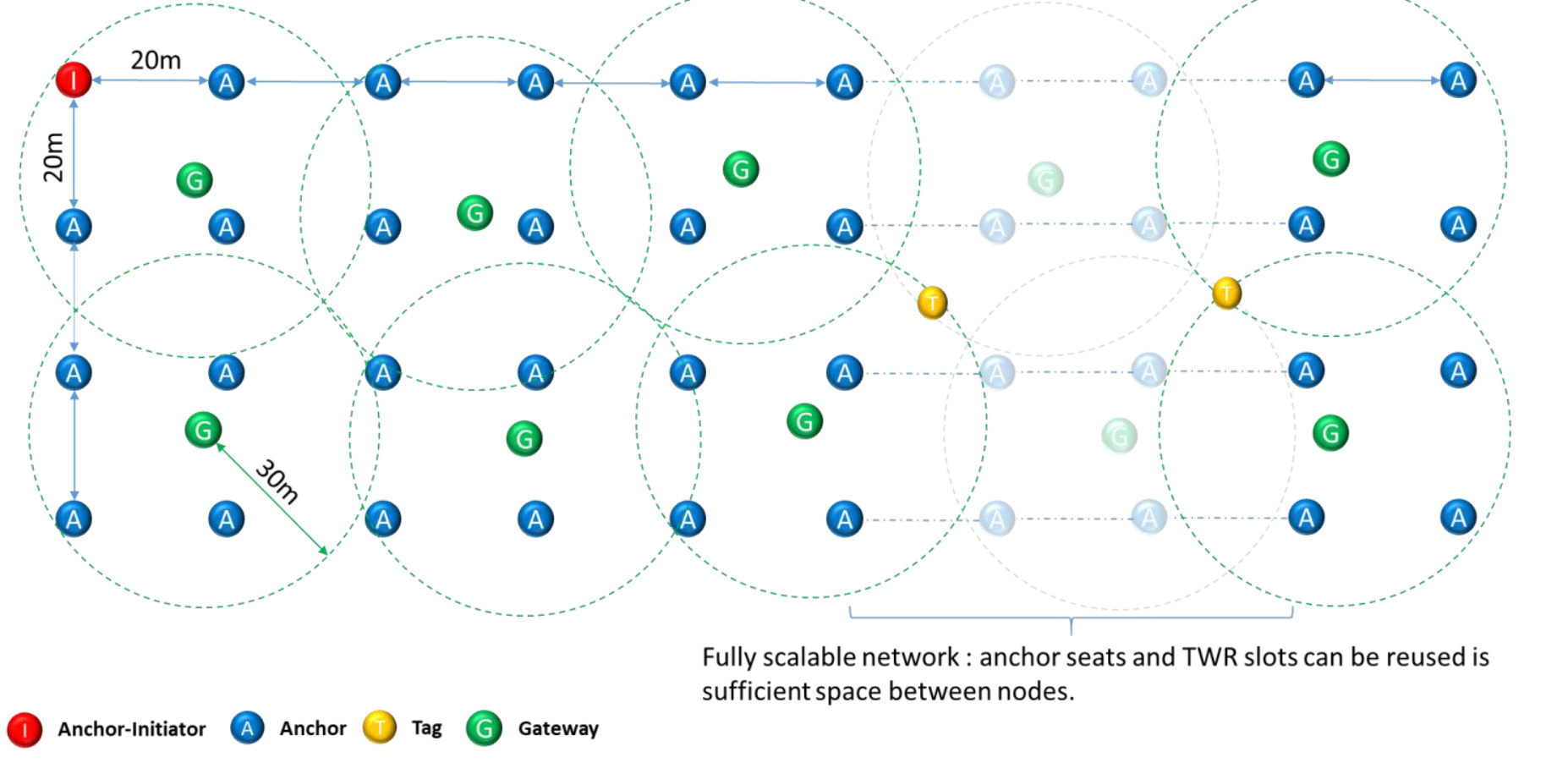
The picture below matches the latest system. As you can see there are several gateways. A gateway will report information from anchors and tags within direct range. As the network can scale further, you need multiples gateways to ensure full coverage of the network.
Yves. Thanks for your answer and I appreciate a lot! But let me insist on this subject because it concerns a lot.
I understand that it is not up to date but seems that I´ll not be able to provide a solution for a large area. First because, correct me if I´m wrong, there is no need to have more than 4 anchors for each gateway, which means gateway must be in range with these 4 anchors. So what is the big deal to have the topology described in the documentation “system overview” which shows expansion procedure, like the picture bellow. Why they didn´t make this information clear there ? It is quite confusing because it leads to another interpretation , don´t you think ? In this way, if we follow the rule you explained, there will be high concentration of anchors around a gateway (which is not shown in the picture). So the distance between anchors should be very short, isn´t it ? Se the link between and anchor initiator and anchor 11. Does that mean that each anchor should be in range with the initiator as well ? If so, why ?
Also, in my understanding and if the anchors are in very short range, air interface will see more collisions because the access method is Aloha and performance will decrease. Am I correct ?
As Kai mentioned before, anchors expansion and gateway are not really related.
The picture you sent is showing how anchors can be deployed, and how anchor seats can be reused to expanse the network.
The picture I sent is an example of a large scale network fully covered by gateway. Note that this drawing assume perfect LOS between nodes, which is not always the case.
With poor LOS, you may need to increase number of anchors locally, and them you may have more than 4 near gateways.
Do not misinterpret the picture you sent. With such an anchor deployment, you would need multiple gateways to cover the full area.
So effectively, a large area can covered but it will need multiples gateways.
Yves. Thanks a lot for your answer. I still have two other questions:
What is your recommendation to connect gateways in a large area ? Can´t be fiber o cable…
When you refer to LOS, in my opinion will only help in increase network availability but, the anchors you put around a gateway, the more collisions you will create, right ? So, care should be take to have a minimum number of anchors in order to keep the minimum interference.
In summary, the data path starts at tag , exchange information with closest anchors , calculate the distance. Now, as the anchor doesn´t send any information, does the tag send location to the gateway directly ? In this case, and in accordance to the previous picture, tag and gateways shall be in range, right ?
Gateway must be connected by either Wifi Or ethernet, and usb for power.
The system can support up to 30 anchors in the same “airspace”. So that means in a very dense area, you can have up to 30 anchors. Realistically a network is spread so this limit is rarely reached. The overall network can have many more than 30 anchors because two anchors can use the same seat within the superframe when there is a sufficient distance between them.
This is correct, both tag and anchors must be in range with gateway. The tag is sending its position to gateways.
No you don’t need to. All nodes (either tag,anchor or gateway/bridge node) will have the same panId. There will be only one initiator within the network. You can configure multiple anchors as initiator but only one will eventually be active as an initiator. The other ones will act as simple anchors.
So basically, you will have a unique network, with multiples gateway and anchors. Anchors will be spread by 20-25m (maximum range in LOS), and you will need to place several gateways so you can cover the full area.
Can the bridge, which is connected to a raspberry, act as anchor ? I mean, if I have 4 anchors and one is the gateway , behave as an anchor and establish a two-way-range to a tag , instead of having 4 anchors + 1 gateway ?
The default power transmission is set to -17 dBm. Is it possible to increase the power to -14dBm which will the limit allowed by regulator (-41.3 dBm/MHz). This would extend the range.
Yves. Once again thanks for your answer.
The power level comes from a documentation from decawave . Let me look for because I have quite many and I don´t have on top of my head now.
So you are saying that the output power is -14 dbm aprox ?
DWM 1001 datasheet v 1.5 page item 2.1.2
“2.1.2 Transmitter Calibration
The DWM1001C is calibrated in module production, the calibrated values are permanently stored in the DW1000 OTP. This module is calibrated to meet the regulatory power spectral density requirement of less than -41.3 dBm/MHz.”
In document “APS004: Increasing the Range of DW1000 based products
…
DW1000 has a receiver sensitivity of between -94 dBm to -107dBm depending on chosen configuration parameters (data rate), hardware setup (carrier frequency offset between Tx and Rx nodes) and the acceptable system performance limits for any particular application (acceptable packet error rate for example). The transmit output power of the DW1000 is limited by design to a maximum value of approx. -35dBm / MHz. This is more than adequate to meet the regulatory maximum limit of -41.3dBm / MHz that applies in the vast majority of geographies where UWB is permitted and provides margin to allow for PCB, balun, temperature, antenna and enclosure losses.
The receiver sensitivity of DW1000 based products can be improved to increase communications range by the addition of a suitable low noise amplifier (LNA). The insertion of an LNA amplifier into the receive path between the receiver antenna and the RF pins on the DW1000 can typically result in a 3-4 dB improvement in receiver sensitivity. This is achieved by lowering the receiver noise figure.”
I know that it is possible to use LNA but the paragraph above makes me confusing. That´s the reason I asked you about increasing power. I was thinking that if the TX power is -35 dBm/MHz, there would be a margin to push to the limit which I supposed to be bellow 14 dBm
I remeber that I saw in a doc that the TX power is -17 dBm but I still don´t find it.
Another point is: Can I use the “smart TX” as described in DWM1000 User Manual with 6.8 Mbps ? If so, will I improve in 6dB above the -14 dBm that is the maximum allowed ?
The DWM1001C are calibrated at manufacturing to ensure they comply with the regulation and the limit of -41.3dBm/MHz.
The PANS software which I believe you are using is already using smart Tx.
Basically when using DWM1001C and PANS there is not much the user can do to increase the power and any increase would most likely violate the regulation limit anyway.
If you are looking for better range, you could use diffrent RF config such as channel, preamble, data rate but note that Decawave’s certification for DWM1001C is valid only for CH5 PRL128 PRF 64 6.8Mbps.
Yves. Thanks for your quick answers. I´m sorry pushing you with so many points but some aspects in documentation are not so clear to me. As the problem I have is related to outdoor environment I´m studying the possibility to improve performance (I know all the story about FCC regulation but this is another aspect that I´ll have to deal with our local regulatory in Brazil).
Again more few questions:
Can I assume that smart TX is enabled by default ?
In documentation APS006-part-2-NLOS operation, many of their examples use frequency of 4GHz. So, if it is not even certified by FCC, why they are using it in the documentation ? Are they planning to certify ?
Following , on page 27, appendix 1, there is a table of received powers x distance but it is assuming the same TX power of -14,3 dBm for channel 2 and 5. I think that ,acoording to the FCC compliance test documentation, page 10, spurius radiated emission, frequency 3100 - 5925 MHZ should be -51,3 dBm/MHz. So power tx should be lower -14,3 dBm in their examples, right ?
Another point that concerns be is the situation where someone holds a tag close to the body. The body absortion ranges from -15 to -30 dB which is quite a lot. Now suppose that you are operating at 6,8 Mbps, antennas gain are -1.1dBi (average), which using Friis formula, will give me a range of 30m and sensitivy is -95 dBm. Now if I have a direct path between tag and gateway, 30 meters range will work. But what happens if you turn around ? That tag TX will have an attenuation of 15 - 30 dB and the direct path will not work. In this case, either reflections on ground can happen and achieve the gateway or in worst case scenario, I will have to put a lot of gateways such that in any situation the tag will have a direct path to any gateway ?