We are working on installing anchors in a large facility. We have found ideal positions where the anchors need to be installed. What is the easiest way to find the absolute location of the anchors. We did it with tape measurements to an accuracy possible. But, that is quite cumbersome. Is there a easy way to find absolute anchor position? How accurate the position of the anchors should be?
1 Like
Hi Jannam,
We are usually using calculating coordinates from a plan of the building and verifying their placement with a laser meter.
Anchors should be as accurate as possible to make sure sure the trilateration will succeed. From my experience about 10 cm accuracy is ok, but less is better.
Yves
We could write a book on anchor survey techniques.
The easiest survey is when anchors are installed in a suspended ceiling. The grid works forms a natural measurement system and all you had to do was measure offsets from the grid and count tiles. In the USA, the grid is 2 ft (609.6 mm) spacing for example. The accuracy of the grid spacing is quite high due to the stamping of the rails with precise joint features. You have to be aware if the ceiling grid work changes alignment in the middle.
Most of our installs don’t have suspended ceilings, so we are back to using more general methods.
In the early days, our best method was laser plumb bob to marks or masking tape on the floor under each anchor, then tape measure or laser measure to reference axis (such as a walls). We’d also measure floor to anchor using a laser measure. This worked best with a flat floor and with open spaces. It produced a reasonably good survey, but was time consuming, and sometimes you couldn’t be directly under an anchor, or didn’t have a flat floor (think arena or theatrical stage).
More details on the laser plumb survey approach plus some general survey and anchor placement insights:
https://cuwb.io/docs/v3.3/application-notes/anchor-positioning-and-survey/
We then got a Total Station which revolutionized our survey methods. A total station is an optical survey device which combines a theodolite (measures azimuth and elevation angles very accurately, 5 arc seconds or better) with a colinear laser ranger. It is an amazing piece of equipment. Here is an example device:
https://www.topconpositioning.com/total-station-solutions/standard-total-stations/gm-50
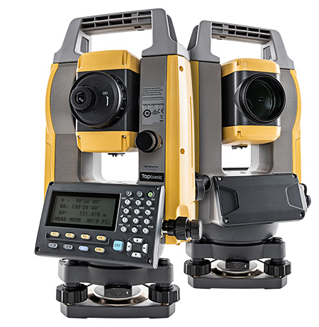
In basic terms, the total station locates any point in 3D space you can illuminate with a laser to a precision of about 2 mm. This is plenty for UWB anchor surveying. The unit above is about $US 5000. There are Chinese versions for under $US 2000 (one we have briefly used is MATO 602R, clearly less quality than the TopCon we normally use, but worked okay).
There is a learning curve and a technique to using a total station which is too involved to describe fully in this post (you can find tutorials online). The basics are that you have to have references in your environment, called foresight and backsight, which define your coordinate system. You locate those and then you shoot the anchors visible to the total station. Then it is a bunch of trig to figure out the anchor locations in 3D. Ideally, the total station communicates the data to a PC via serial, USB or Bluetooth, so there is no hand entry (and possible errors). We wrote our own script to receive the data, do the computations, and prepare a survey file for our CUWB system.
In some cases, one setup of the total station can shoot everything at once. Examples might be a basketball arena with the total station mid court. You shoot the court boundary as the references, then all the anchors, do the math, you are done. In some cases, anchors will be visually blocked from the total station so you have to do two or more setups to see them all. No problem as long as the foresight and backsight remain in view at each new setup location.
In yet other cases, you have to survey a space that is so big or complex you can’t see the original foresight and backsight. In these cases, you have to place new references down in the prior setup that you will work off in the next setup. Here at Ciholas, we developed whole set of target devices for that purpose which work well to reference corners, marks on the floor, corners of athletic fields, or targets on the wall.
Our biggest survey ever was for the Museum of the Bible which involved 600 anchors on 7 floors over 43,000 m^2 (430,000 SF) of floor space. The foresight and backsight were the corner of the elevator shafts since that was visible on every floor. The worst floor was floor 3 which involved a whole series of small interconnected rooms (the Hebrew Bible Walking Tour). This required 27 setups of the total station to survey the entire thing which resulted in a total error accumulation of under 10 mm which is far better than we expected. We have done warehouses up to 100,000 m^2 as well, which are pretty easy by comparison. There was no way we could have surveyed these large and complex sites without a total station.
A key to good survey by total station is having an anchor design which naturally supports laser reference points. Our present DWETH anchor is okay for this, not great, but our next generation anchors have been specifically designed to facilitate laser and total station surveys.
What about auto survey? Everybody likes the idea of a system which can perform its own survey and you can avoid all this measurement hassle. In small systems, auto survey can work reasonably well and we have developed that in the lab. However, auto survey just doesn’t work for large systems, ones which are bigger than a few network radio diameters, or systems with high precision requirements. The small errors between anchors accumulate and create a distorted final result, usually a concave or convex warped surface that should be flat. So a truly professional system requires external survey.
Mike Ciholas, President, Ciholas, Inc
3700 Bell Road, Newburgh, IN 47630 USA
mikec@ciholas.com
+1 812 962 9408
We’ve run through a similar learning experience on survey techniques.
Since our initial testing was outdoors and fairly large distances between points we rapidly abandoned laser ranger finders, aiming them accurately over longer distances in the sunlight is very tricky.
Instead we used RTK GPS for positions which worked reasonably well but involved a conversion from latitude/longitude to meters and was still fairly manual.
We’ve ended up with a total station as well only we use a robotic version. This allows us to have the total station automatically track and measure a prism. We 3d printed a holder that fits over the anchors and positions the prism over them in a repeatable way. Survey then consists of 1 person walking to each anchor in turn, placing the prism on it and pressing a log button on a tablet computer. At the end of the process you get a text file of x/y locations which we can drop directly into our setup software.
Its more expensive than a non-robotic total station but reduces the skill required to operate it. It can also be used to automatically track and log positions at around 1 Hz giving a good truth measurement for testing as long as you aren’t moving too fast.
Indeed, the accuracy with which you have to hold such a device, and being unable to see the laser dot in sunlight, does make it impractical outdoors.
Requires conditions suitable for GPS, namely good open sky, which many places do not have (think large sports stadium, for example). RTK GPS won’t achieve the same accuracy as a total station. Lastly, RTK GPS requires physical access to each anchor location to place the RTK GPS receiver.
The problem with this method is that it requires physical access to the anchors. In most of our installations, that is impractical as the anchors are mounted up high in the ceiling structure or on poles or towers. To get to many of those anchor sites, it requires a man lift.
Our solution to this is to make anchor enclosures with good geometry suitable for a reflectorless total station. This allows a total station to be setup in the general middle of the active area and shoot all the visible anchors. We can thus survey without having to place a prism near the anchors or being close to them at all. This makes survey very quick and can be done multiple times by one person at the total station. You don’t need a robotic total station, which are expensive, but a far lower cost general total station.
An example are the 54 anchors we did for a basketball arena. Being indoors, RTK GPS is out. Having that many anchors in the ceiling structure made it hugely impractical to place a prism at each one. But with one total station setup in the center, can shoot all 54 in quick succession. A datalink from the total station to a PC, plus a script to convert the readings to the final survey coordinates, makes the process efficient and error resistant.
Mike Ciholas, President, Ciholas, Inc
3700 Bell Road, Newburgh, IN 47630 USA
mikec@ciholas.com
+1 812 962 9408
Instead we used RTK GPS for positions which worked reasonably well
Requires conditions suitable for GPS, namely good open sky, which many places do not have (think large sports stadium, for example). RTK GPS won’t achieve the same accuracy as a total station. Lastly, RTK GPS requires physical access to each anchor location to place the RTK GPS receiver.
I agree with every one of your points. But for initial system development and testing a couple of cm was good enough accuracy, physical access wasn’t an issue and we were running outside so that we could use GPS as a truth reference. We’ve moved away from it now but for initial development it was a good option since it was relatively cheap and good enough for what was needed at the time.
The problem with this method is that it requires physical access to the anchors. In most of our installations, that is impractical as the anchors are mounted up high in the ceiling structure or on poles or towers. To get to many of those anchor sites, it requires a man lift.
Generally you have physical access to the anchors when you are installing them. It’s a little hard to install them otherwise. As long as you survey at the same time as installing them this isn’t an issue.
But for some situations I can see how that may not be the most practical solution.
We did design our housing with features to allow the antenna location to be measured using a reflectorless system but since our target market includes some people who want the ability to move / set the system up themselves rather than it being a one time install we wanted to de-skill (is that a word?) the survey side as much as possible. The robotic system does that.
We’ve got it down to under 1 hour from arriving at a site to being up and running and generating positions using UWB. That includes geo-referencing the whole thing so that you can transition cleanly between GPS and UWB. That’s not a 54 anchor system and it’s not mm accuracy but then that’s not what the target market needs.
Ultimately the best install method is going to depend on the use case.
If you are doing a large install, say 600 anchors at a museum under construction, survey during install is a non starter. The install is happening during construction and usually by electricians trained in general network wiring. Keeping a total station setup and aligned all during that activity (which can take weeks or even months) is impossible.
In some installs, it is impossible to gain physical access to the anchors once they are in the working position. A common example is anchors on a lighting truss for a theatrical setup. The lighting truss is built and tested at near ground level, then winched into place above the stage. You often can’t get a lift that will reach the anchors, and you can’t survey at ground level prior to winching. So the only option is to survey afterward without access to the anchors.
Once we have our total station leveled and setup, it takes about 30-60 seconds per anchor to survey. Focus, aim at anchor reference point, perform measurement, enter anchor serial number into PC script, move to next anchor. The script takes care of all adjustments between the laser target on the anchor and the actual antenna reference point inside the anchor. We always make sure to hit the location references (foresight and backsight) both at the start and at the end to confirm total station did not move for every data set. If the second measurements differ fro the first by too much, we do the measurements again.
The reflectorless total station also allows us to measure the location of general objects in the working environment even when not physically reachable. Walls, doors, poles, light fixtures, etc. We can also place test points and measure them for future system checks. If we are doing a complex survey, say a hospital with many rooms, we place reference markers in the current setup which will then be used in a future setup so we can move the total station to a new vantage point.
I’m not really seeing the reduced skill required having to position a prism at the anchor with a robot total station versus sighting the anchor from a general total station. The robot total station will cost a LOT more as well.
Mike Ciholas, President, Ciholas, Inc
3700 Bell Road, Newburgh, IN 47630 USA
mikec@ciholas.com
+1 812 962 9408