LNA stability at channel 5 . Alternate LNAs

Hi ,

One of our project we are using DW1000. We have to get at least 50 meters on channel 5. We did the range test in the field but we got only <30 meters with WB002 antenna. To improve the range we plan to put LNA into the receive section. The specified part in the application note is not stable for some of the frequency range. Can you please suggest an alternate LNA for channel 5 or matching and biasing component for the specified part in the application note.
What is the bandwidth of channel 5, which you got 70-meter range?
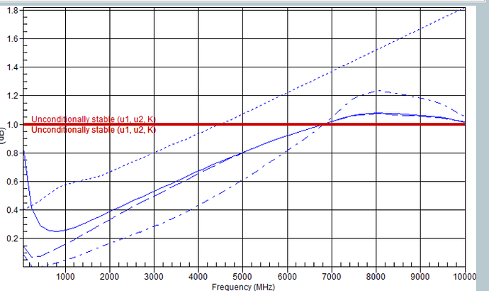
the stability graph of BGB707L7ESD is attached.

-Akhil

Hi ,

For the bandwith used, see the datasheet.

30m isn’t a lot, what Software is in the EVB1000? Is it the standard version 3.05 or 3.11.

And what datarate is used?

It should be possible to get passed the 100m when using 110kb/s with either channel 2 or 5.

So please could you say something about the testing environment or even send pictures describing the environment?

What I also like you to do is get to the 30m with the boards and keep walking to see if the ranging starts again at let’s say 40-50m

This because some environments shown that reflections can interfere destructively, causing loss of communications in regions known as Freznel zones. So the maximum range over which communication is achievable depends very much on the environment, which makes is difficult to specify on a datasheet.

Regards
Leo

Hi Leo ,

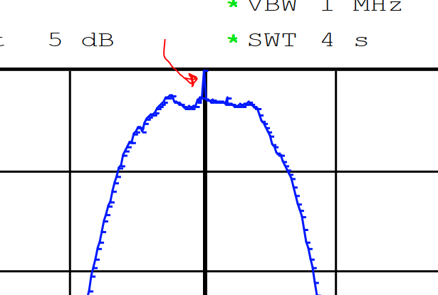
The datarate used is 850 meter. From the theoretical equation also i got the range around 40 meter. From the datasheet the sensitivity of the chip is -101 dBm for 850 Kbps. In the datasheet given spectrum reaches to -40 dBm/MHz . From our radiated measurement also we found one peak reaches to -40 dBm/MHz so we reduced some dB to get -41dBm/MHz. Then I integrated the PSD in the frequency band 500 MHz to get average power which is -17.7 dBm/500MHz. In decawave application note they took -16 dBm/500MHz there is 1.7 dB difference in actual measured result and decawave took in application note. If we consider 0 dBi antenna then RSSI at 50 meter will be -101 dBm/500MHz . In PCB there is one balun , which has 1.5 dB insertion loss in the band so the sensitivity becomes -99.5 dBm/500 MHz . so the theoretical range will be 38 meter . There will be some connector loss also. after accounting it into consideration is 30 meter is maximum range for DW1000 chip? for channel 5, 500 MHz bandwidth??

channel%205
-Akhil

Hi Akhil,

A couple of comments here…

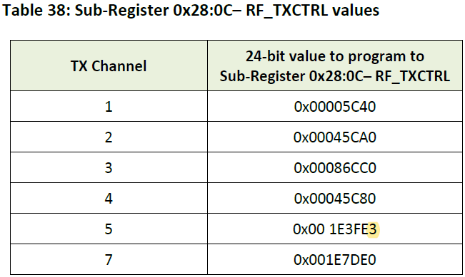
From your spectrum plot, the large spur at the carrier frequency is likely due to LO carrier feedthrough and can be removed by making this register change for Channel 5 (now in the latest User Manual version).

image

By avoiding having to dial back the Tx power due to this spur, you should get a couple of dB additional link margin to hopefully get you closer to your range target.

I know plenty of customers have used Infineon BGB707L7 and so I would have thought that it can operate stably in Channel 5. Unfortunately, we don’t have reference design for this amplifier that we can share.

Another LNA that you could look at is Macom MAAL-011130. We haven’t validated this in an DW1000 receiver circuit but I’ve used it successfully as a pre-amp for a spec an in a Channel 5 OTA measurement setup. This seems easier to design-in than the Infineon part. I just used a series cap (1.8 pF) and choke inductor (2.7 nH) on the output. It seems to work well for my requirements (a lab setup at room temperature). If you have simulation capabilities you may be able to find a optimal design that’s good over temperature, voltage, etc. variations?

Anyway, hopefully this post will be of use to you. I’d be interested to hear your progress.

Akhil,

In a well designed system without an LNA, you should be able to achieve 50-70 meters at regulatory limits using channel 5, PRF 64, and 6.8 Mbps modulation with short packets (which allows higher peak power in proportion to 1 ms average). We routinely get this performance in our designs when we can fit an appropriate antenna. As the antenna becomes constrained in size or other factors, the range can be reduced. The antenna is the most critical part of the system, but seemingly small errors in other places can reduce range quite a bit, too.

We have used a BJT based LNA in some early designs, which would operate similar to the BGB707 you reference. In our experience, the BJT based LNA designs suffer from poor linearity and can easily be saturated by external signals such as cellular. In one particular case we observed, cellular tower’s signal saturated the BJT LNA and prevented operation as the third harmonic fell right into the channel 5 band. The base junction characteristics of a BJT are inherently non linear and cause lower fidelity factor which hurts UWB performance even when not being interfered with.

Over the past year or so, we have developed a far more robust and effective LNA based on a pHEMT JFET device with a 0.3 dB noise figure, about as low as uncooled devices can get. This device increased linearity by 10-15 dB over the BJT since JFETs are inherently more linear than BJTs. We further fitted this with a prefilter to knock out bands below our channel of interest (adjustable by BOM to cut out either below 3 GHz or below 6 GHz depending on whether you want the low bands or not). This has made the LNA far more robust to interference (at least 40 dB better against cellular) and improved our range over what a BJT can do. We have now put this into 4 different designs with great success in each, so it doesn’t seem particularly finicky in layout or to develop self oscillation.

In rough terms, the new pHEMT LNA doubles the range. We can get 100-150 meters reliably at regulatory limits, and in some cases can see reception out to beyond 200 meters. The range limit is often due to reflections and destructive interference than an actual signal strength loss, so it matters a lot how you test range and in what environment it is. Counter intuitively, a super clean environment (say in outer space with no multipath) will have lower range than a more cluttered one as the multipath signals help the receiver capture the packet.

The pHEMT LNA uses about 15 mA at 3.3 V, so it does cost some power, but not a huge amount. It is only on during receive. As part of the design, we also selected some very good RF mux chips to go with it. The BOM cost is not excessive, similar to a BGB707 design. The LNA can cover all the DW1000 bands, and also works for the higher bands that may be supported in future UWB chips.

Given the investment we have made in the LNA design, we do not give that design out for free. Please send me email (mikec@ciholas.com) if you would like to discuss how you could license this design for your project and perhaps how we could provide design assistance for your project. We’ve built dozens of custom DW1000 based systems so we know what works and what doesn’t.

Mike Ciholas, President, Ciholas, Inc
3700 Bell Road, Newburgh, IN 47630 USA
mikec@ciholas.com
+1 812 962 9408
2 Likes

Hi mike ,

thanks you for your reply . Our device is a battery operated device so current consumption matters. I believe linearity is directional proportional to current consumption. i designed an LNA using BFU710f , which has maximum Ice is 10 mA. I used 2 mA for biasing. Did you calculated linked budget? which equation is used to calculate link budget.?

-Akhil

Battery usage is almost always critical for tags. It can sometimes be critical for anchors if they are not line powered in some way (say PoE, or some other form of power).

Linearity does improve with increasing current and you will find many LNA designs with very high currents out there (> 50 mA) which have high linearity and can handle strong out of band signals. But linearity also improves with using JFET devices over BJTs. At the same Icc/Idd, the JFET seems to be about 10-12 dB higher linearity (that is, takes about 10-12 dB stronger interferer for similar harmonic splatter to occur).

We currently run our LNA at 15 mA Idd, 3.3V, which is 50 mW. When the DW1000 is in receive, it is about ~500 mW by itself, no LNA. So the LNA is a 10% adder to the power requirements, which seems tolerable in most applications. You can, of course, turn down the Idd to any level you want by how you bias the JFET which saves power and sacrifices a bit of linearity (really, not much, maybe 2 dB to go down to 5 mA). Our LNA turns off when DW1000 is not in receive, so power is only used when actually receiving.

As to link budget, we compare the non LNA device to the LNA equipped device and find it gains about 6-7 dB more sensitivity. That is, we can attenuate the transmit signal by that much more and still have it received. That’s a lab test, and then we take it outdoors and do a real range test and find the LNA roughly doubles the reception range. The outdoor test is subject to many more variables and site sensitivity, so harder to express in terms of dB, but we like doing it as a basic sanity check.

BJTs are popular for LNAs due to low cost and high robustness. JFETs are popular for higher performance. The cost of the other parts (RF muxes, filters, bias, etc) typically dominate the LNA cost, however.

Mike Ciholas, President, Ciholas, Inc
3700 Bell Road, Newburgh, IN 47630 USA
mikec@ciholas.com
+1 812 962 9408