Hello there!
I have recently started tinkering with the DW3000 - currently evaluating it for use cases our company specializes in. I have a few questions regarding the user manual, as it sadly lacks important information or distinction in certain places. I’d appreciate any breadcrumbs here that you can offer.
Thank you kindly in advance!
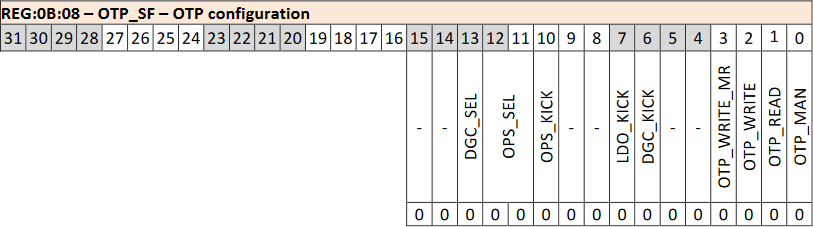
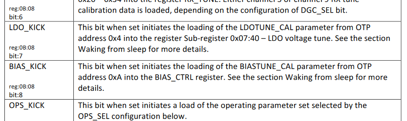
BIAS_KICK
The user manual (8.2.12.3) states that BIAS_CTRL (11:1F) can be loaded from OTP using BIAS_KICK (0B:08:8). While it does not show up in the bitfield, the detailed field descriptions contain the entry.
However, the reference implementation (deca_device.c:687) both triggers automatic loading from OTP and loads the value into the register manually. Why is that? One of these methods is certainly superfluous.
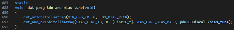
Note that LDO_BIAS_KICK here is defined as 0x180, which would set both LDO_KICK and BIAS_KICK.
RX_CTRL
There is, for whatever reason, a magic number (0x08B5A833) set in the reference implementation (deca_device.c:1501) for RX_CTRL (07:10).
![]()
Neither the register nor the constant value itself make an appearance in the user manual - and curiously there is no matching value for channel 5. Is there any documentation anywhere on what this is supposed to achieve?
DTUNE3
According to the user manual (8.2.7.4) the value of DTUNE3 (06:0C) needs to be changed unconditionally from the default value of 0xAF5F584C to 0xAF5F35CC.
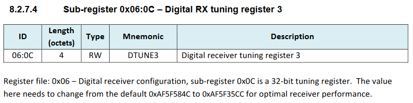
However, the reference implementation (deca_device.c:1453) only changes this value when the no-data STS mode is used.
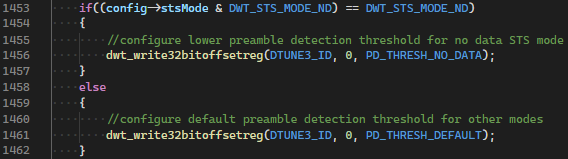
So which is it? Always set it to a constant of 0xAF5F35CC - as per the manual - or only do so conditionally - as per the reference?
LDO_CTRL
The user manual (8.2.8.9) contains LDO_CTRL (07:48), but gives absolutely no details on the contained fields or the specific functions of the mentioned blocks.
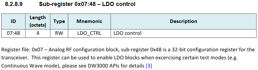
The reference implementation certainly has more information, but still lacks a basic description of their intended uses and when they are supposed to be powered up/down (except for a few comments here and there scattered across the codebase).
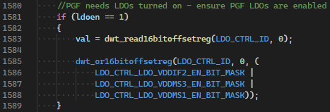
As an example, why do I need these on for calibration, and how am I supposed to learn of this - other than scouring through the poorly documented code?
TX_ANTD and RXANTD
TX_ANTD (01:04, 8.2.2.19 in user manual) and RXANTD (0E:00:0-15, 8.2.13.36 in user manual) are the transmitter and receiver antenna delays, respectively.
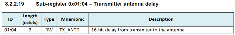

There seems to be a field called Antenna Delay – RFLoop (0x0B) in the OTP memory, that should contain the correct values for these registers.

However, there is no explanation on what this 32-bit field actually contains - as both TX_ANTD and RXANTD are 16-bit values. The reference implementation contains no clues on how to use this pre-configured value and instead uses a fixed value of 16385 for both.
![]()
![]()
It’s safe to say that the mentioned NOTE 2 is no help, either.
I have instead found in the DW1000 user manual a similar pair of fields called TX/RX Antenna Delay – PRF 64 and TX/RX Antenna Delay – PRF 16 - both residing within the 32-bit value at 0x1C in the OTP memory. When reading the aforementioned Antenna Delay – RFLoop as two separate 16-bit values, however, what I got was a value that was suspiciously high. Dividing by two got me a lot closer to the default value used by the reference implementation, so I figured that should be the value I have to use.
To sum it up, here is how I acquired the final transmitter/receiver antenna delay:
- I’ve read the value of
Antenna Delay – RFLoop. - I’ve taken the side corresponding to PRF 64 (according to the DW1000 user manual), since I’m using a 64 MHz preamble (code 9).
- I’ve divided the value by 2.
In my case, this gave a value of 16379 for PRF 64 and 16361 for PRF 16. Do these seem correct - especially the fact that it’s higher in the case of PRF 64?
Is this the correct way to find the delays to begin with? If so, why are there separate transmitter and receiver antenna delays, if the two values are always going to be same anyway?
Furthermore, after running a few tests in a double-sided two-way ranging scenario, I’ve concluded that I get consistently more accurate measurements of flight time (and thus distance) when using the default value of 16385 (as per the reference implementation) instead of the value acquired (using the method described above) from the OTP memory. There is obviously a chance that my ranging implementation is erroneous, but let’s not get into that just yet - I’m hoping there’s a simpler explanation here.
The topic DW3000 User manual missing information present in the drivers has already inquired about LDO_CTRL, but it was unfortunately left unanswered.


 , i will head to see my original thread