Unable to achieve advertised precision (+/-10cm), getting +/-1m on DWM1000

I am currently participating in a IoT project that uses a hardware platform based on the Espressif ESP32 chipset, with a pluggable module architecture, one of which contains a Decawave DWM1000. The project, of course, involves locating a tag using a couple of anchors with known coordinates, and I am currently performing tests for distance accuracy. However, I am yet to achieve the expected precision in the distance measurement, because the calculation result fluctuates by 50 cm to 1 m, and even sometimes spiking to 2m errors, all with the anchor and tag devices (one of each) completely stationary and in direct line of sight of each other.

  • The ESP32 board is powered from a 5V, 2.4A USB power charger for both anchor and tag devices
  • The ESP32 board has WiFi active, both as a debugging tool, and as a means to transmit MQTT messages containing the calculated position to plot on a map.
  • The DWM1000 plug-in board, as far as I know, runs on its default internal oscillator. No external or temperature-compensated oscillator has been added to the board.
  • The code is supposed to use an revised version of asymmetric two-way ranging (all timestamps are in Decawave clock units):
    • Tag sends a poll packet with its own EUI every 500ms to announce itself to any anchor in range, and stores the transmission timestamp internally on TX interrupt
    • Anchor receives packet, takes note of reception timestamp, waits a bit for radio silence, transmit a poll acknowledge, and stores transmission timestamp internally on TX interrupt
    • Tag receives poll acknowledge, takes note of reception timestamp, and sends a range request packet containing the poll transmission timestmap, poll ack reception timestamp, and an estimate of the impending range packet transmission timestamp using the current timestamp plus 3000us converted to Decawave clock units, plus the current TX antenna delay. This transmission uses the delayed-transmission feature of the Decawave.
    • Anchor receives range request packet, takes note of reception timestamp, and calculates the time-of-flight using the asymmetric two-way ranging formula
    • Anchor converts time-of-flight to distance using the library conversion constant, then (supposedly) corrects the distante using the reception power measurement, and transmits the value back to the tag

The Decawave-specific code has two layers. The lower layer is at https://github.com/yubox-node-org/arduino-dw1000-ng/tree/alex-concurrency-workaround2 which is a personal fork of the arduino-dw1000-ng code with tweaks to make it stable on the ESP32, which include at least the following changes I made:

  • 846891bd744172bd8e3859303fff4ad3fe446c7d Use a separate mask to clear SYS_STATUS bits, otherwise I lose event bits
  • 08f7a432bc537829aee613a4427cc35056b8932d Move direct interrupt handling to a separate ESP32 task
  • f34ca830c775df4ce149d996fa0ef8f6894f0efd Use 64-bit values to handle Decawave timestamps, rather than risking truncation of 5-byte values to 4-byte longs
    Additionally, in searching for the cause of the fluctuations, I am now correcting for the following conditions not addressed by the upstream Arduino library:
  • The 5-byte Decawave timestamps wrap around every 17 seconds, so two timestamps measurements may fall on opposite ends of the wraparound. This is guarded-for and fixed in my code.
  • The Decawave User Manual states in section 3.3 Delayed Transmission that the delayed transmission timestamp will ignore the lower 9 bits of the start-of-transmission value. My code adds the required value so that the resulting future transmission timestamp will have the lower 9 bits set to 0.

As I have noticed that the reception timestamps get scrambled by packet collisions, I have (for now) kept the test to one anchor and one tag. Yet the fluctuations persist.

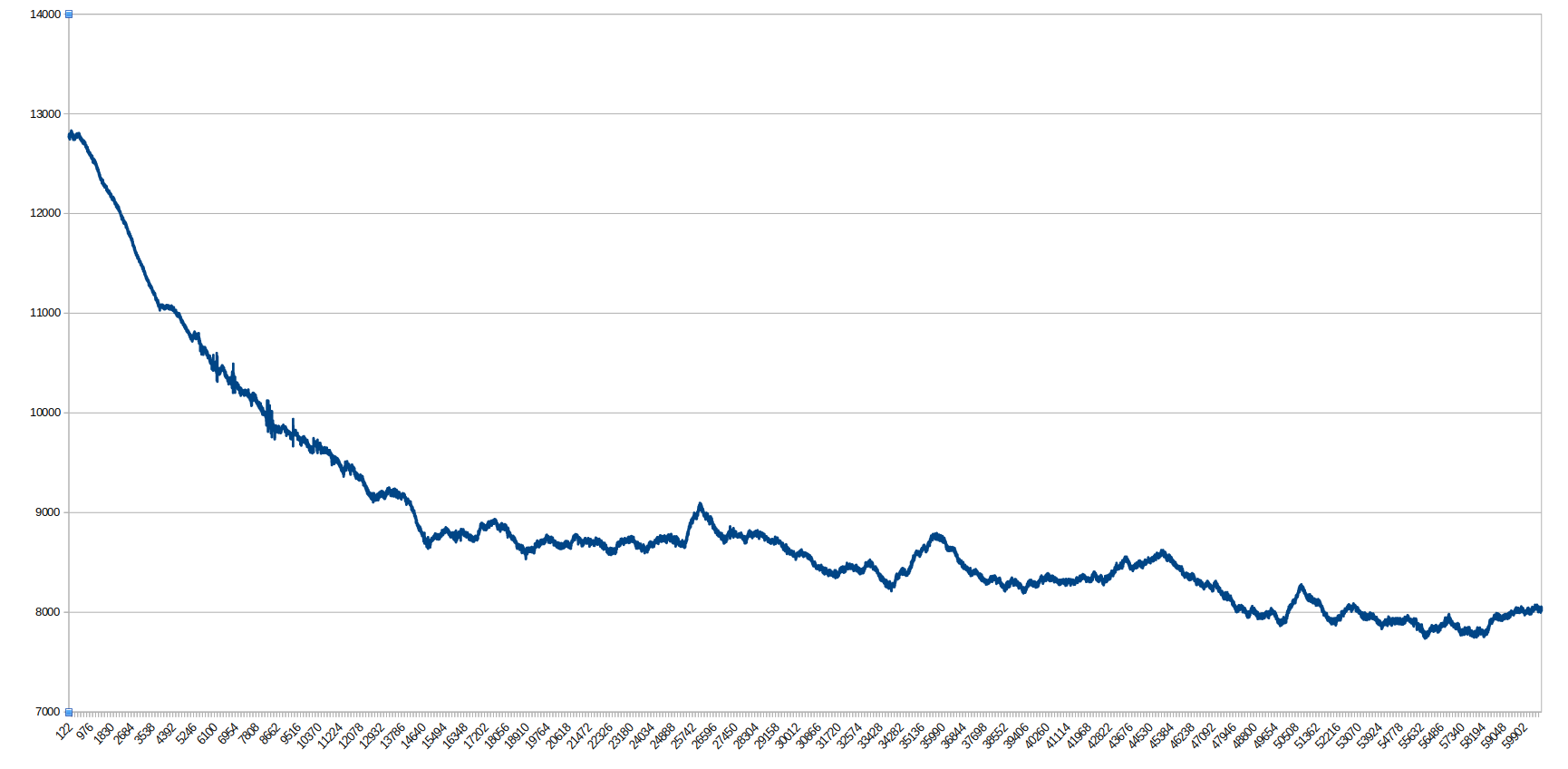
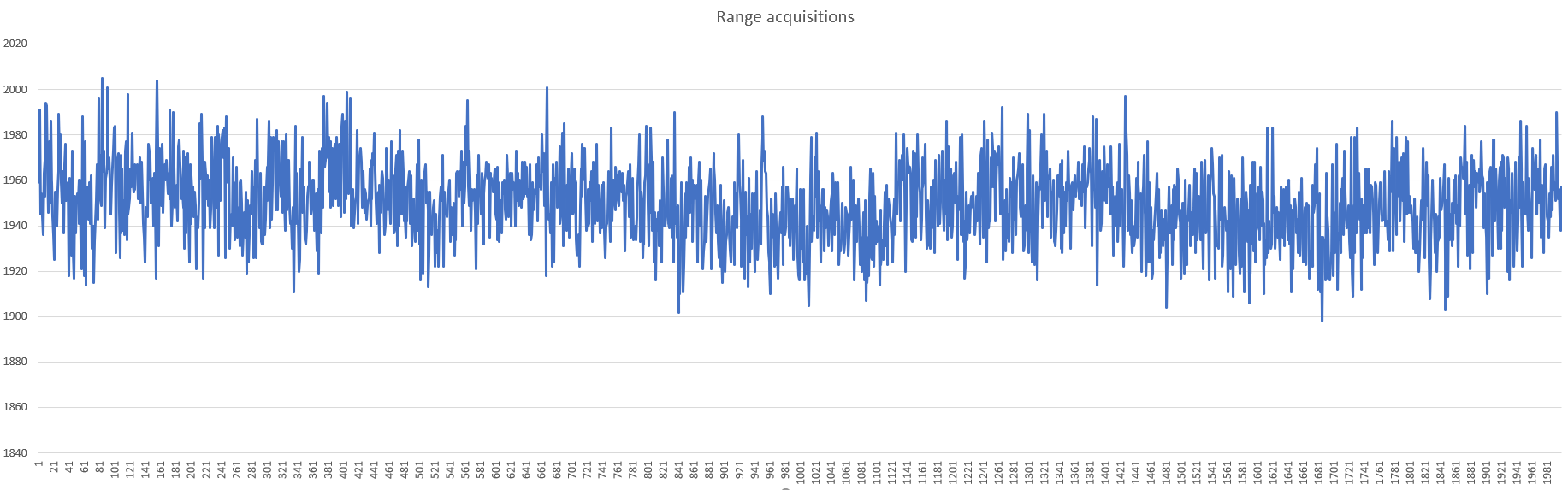
As stated previously, the problem I am seeing is that the result of the calculation fluctuates by up to 1 meter, even at the distance I attempt to use for a simple antenna delay calibration (6.6m). As a result, the antenna delay calibration converges slowly, and then does not stay in one value, but fluctuates across more than one hour of attempted calibration. Additionally, even with the calibration at the known distance, a shorter distance also fluctuates around an incorrect distance (5m measured as 5.5m, 4m measured as 2.9m). The reception power correction appears to be on the order of a few tens of centimeters, but the errors I am seeing are much greater, and variable.

I have read about the influence of temperature in the internal oscillator, and I have attempted to calibrate after a delay of a few minutes, but this does not stop the timestamp measurements from fluctuating.

What other factors (in software or hardware design) could be influencing and causing the fluctuations in measured distance?

There are many possible causes of this problem, but let me suggest a simple one you should check: failure to account for the transmit time quantization.

If you set a delayed transmit to occur at some DX_TIME, the lower 9 bits are not honored, the transmit departure time is quantized to 512 tick boundaries, roughly 8 ns or 2.4 meters. If you don’t account for the transmit quantization, and you do TWR, your distances will fluctuate up to 2 meters at worst, and commonly around a meter or so. This seems to describe your situation exactly which is why I mention this issue.

One way to detect this is to print out the transmit and receive times in hex. For DS-TWR, there are 6 values. All of the TX times should end in 9 zero bits, one of the following forms:

0x…000
0x…200
0x…400
0x…600
0x…800
0x…a00
0x…c00
0x…e00

If the TX time values you are using don’t end that way, you are using the wrong values in your distance computation.

The above issue will be relatively insensitive to distance between nodes and antenna orientation. If you problem is sensitive to antenna orientation and/or distance, then it is an RF problem. I do not think this is the case based on what you have said.

If the above issue is not the problem, then my focus would be on the 38.4 MHz crystal signals to the DW1000 chip. Any noise in those signals can lead to wandering PLLs in the DW1000 which can show up as unstable timestamps.

One way to check this is to take a known good transmitter (say an EVK board) and program it to transmit packets at a fixed and constant interval using delayed transmit. Then receive packets from your board and look at the delta RX_TIME value (subtract previous from last). You should find that interval (assuming no dropped packets) is very stable within about say 15 ticks or so. If that is NOT the case, then you have an issue you have to resolve. You can also turn this around and go the other way (your board transmits to known good receiver) to double check if it is only an RX problem, a TX problem, or both.

If my suggestions above didn’t help you find the problem, we are very familiar with the ESP32 and are Decawave experts, so if you pay us to examine your system, we will find the problem quite quickly.

Mike Ciholas, President, Ciholas, Inc
3700 Bell Road, Newburgh, IN 47630 USA
mikec@ciholas.com
+1 812 962 9408

I thought I was already taking the 9-bit issue into account when collecting the TX times. All of the TX times are using immediate (not delayed) transmission, except for the one timestamp that is embedded in my RANGE packet, because I have already transmitted that one before the TX timestamp becomes available. For that one, I was already clearing the lower 9 bits, or I attempted to. I will check my code more closely to see if it actually does what I believe it does.

I have checked the timestamps sent by the TAG. What I have noticed is that not only timestamps resulting from delayed transmission, but ALL transmission timestamps, are quantized by 512, and then incremented by the programmed antenna delay. This is more or less what I expected to happen.

A few hours of observation shows me something strange. The second-by-second measured distances sort of remains within +/-20cm of a mean, but the mean itself wanders over the span of tens of minutes. For example, as I write this, I have a tag and an anchor. The true distance, as measured with a tape, is 2.60m. I have seen the calculated distance fluctuate from 1.90m to 2.20m across a few minutes of observation. But when I checked about 20 minutes later, the same two devices calculate 2.39 to 2.50m, without having been moved at all. Still later (around 45 minutes from first observation), the fluctuation is again around a mean of 2.10m, and right now is at a mean of 2.0m. The pro0grammed antenna delay has not been changed during the observation. What I expected to happen if everything worked correctly is for the mean NOT to wander.

I do not have an EVK board at hand, or other known-good transmitter. What I did was to program two Arduino sketches. The first one does not receive any data, and just uses the Delayed Transmission feature to program a packet transmissión every 100 milliseconds. According to the transmitting Decawave, I am achieving an exactly precise transmission interval of 0x8323be00 between one frame and the next. The other sketch does nothing but receive. When receiving a packet, the sketch prints the absolute timestamp value, followed by the difference between this timestamp and the last received one - the real interval as seen from the RX side, and as a reference, the difference between this interval and the expected one (0x8323be00).

What I expected to see is a non-zero difference between the expected interval and the real one, but a difference with only small fluctuations over time. Instead I see this:

0x000000664a6f475c (0x8323e359) - 9561
0x00000067c74b6411 (0x8323e34b) - 9547
0x00000069442780a3 (0x8323e36e) - 9582
0x0000006ac1039d56 (0x8323e34d) - 9549
0x0000006c3ddfba13 (0x8323e343) - 9539
0x0000006dbabbd6d5 (0x8323e33e) - 9534
0x0000006f3797f38f (0x8323e346) - 9542
0x00000070b4741039 (0x8323e356) - 9558
0x0000007231502cea (0x8323e34f) - 9551
0x00000073ae2c49a0 (0x8323e34a) - 9546

After a few minutes I see this:

0x00000018450bd9b0 (0x8323e3f3) - 9715
0x00000019c1e7f5bf (0x8323e3f1) - 9713
0x0000001b3ec411cc (0x8323e3f3) - 9715
0x0000001cbba02dd2 (0x8323e3fa) - 9722
0x0000001e387c49dd (0x8323e3f5) - 9717
0x0000001fb5586605 (0x8323e3d8) - 9688
0x000000213234821a (0x8323e3eb) - 9707
0x00000022af109e29 (0x8323e3f1) - 9713
0x000000242becba3d (0x8323e3ec) - 9708
0x00000025a8c8d649 (0x8323e3f4) - 9716

After still more time, I see this:

0x000000416334a745 (0x8323e2e8) - 9448
0x00000042e010c458 (0x8323e2ed) - 9453
0x000000445cece157 (0x8323e301) - 9473
0x00000045d9c8fe6d (0x8323e2ea) - 9450
0x0000004756a51b80 (0x8323e2ed) - 9453
0x00000048d381388e (0x8323e2f2) - 9458
0x0000004a505d559b (0x8323e2f3) - 9459
0x0000004bcd3972bd (0x8323e2de) - 9438
0x0000004d4a158fd0 (0x8323e2ed) - 9453
0x0000004ec6f1acd2 (0x8323e2fe) - 9470

Not only the fluctation exceeds the 21-tick interval threshold over a short timespan, but also the mean of the difference wanders through time.

Here is a graph made from a log of a sample run of the programs:

Can an asymmetric two-way-ranging algorithm deal correctly with this wandering difference? Is this wandering a symptom of something wrong with the board design, or should it be expected?

Not that this necessarily changes your test validity, but 100 ms in DW1000 ticks is 0x01 7cdc 0000.

A tick is 1 / (38,400,000 * 13 * 128) seconds.

For a delayed transmit interval of 0x00 8323 be00, that works out to about 34.4 ms interval. Going faster is better as will be clear here shortly.

Good test and you got good data.

My assessment is that your numbers are actually mostly reasonable. Your system is actually not failing or broken. You’ve simply discovered how crystals work.

The 34.4 ms delay between transmissions is a long time in DW1000 terms. So you will see wide variation in the receive interval due to crystal drift between the two devices.

For example, a 20 tick variation is 313 ps of time. Over 34.4 ms, this is a drift of 9 ppb, 9 parts per billion. That is a natural drift rate of a crystal, particularly when consider it is two crystals that can drift (4.5 ppb up for one, 4.5 ppb down for the other, say)

If you speed up the process, sent packets faster, then you give the crystals less time to change frequency and you will see improved tightness of the results. When we do quick DS-TWR, we complete the entire process in less than 1 ms which is why we get very tight results.

Why do crystals drift? Mainly it is a temperature dependence. So the reason you see these long duration changes is that your devices are changing in temperature slowly and thus the clock offset between devices is drifting.

Indeed, your curve shows this very clearly:

When you start, the DW1000 chips and boards are “cold”. The receiving side will get warmer (using more power) than the transmit side. From the above graph, we can compute your thermal time constant at about 15% of the X axis in time. The remaining variations are how the crystals respond to small variations in temperature. I bet you could correlate the change in numbers to HVAC system operation as the room temperature moved up or down fractions of a degree. We’ve tracked data which perfectly correlated with our HVAC being on and off.

Your numbers show a low of 9438 and a high of 9722, a wander of 284 ticks. At 34.4 ms, this is a crystal drift of just 130 ppb, not very much, about 1/8 of a part per million!

If you want to have fun with this, set it up, and then blow on one of the boards. Or use a hair dryer or freezy spray to make it run wild. Your numbers will really wander all over the place.

Welcome to the world of crystals! They aren’t the ideal devices we would want them to be.

There’s nothing in the TWR algorithm that can compensate for crystal drift.

I judge your board is not out right broken, you are just observing expected crystal drift.

There are two primary ways to fix this problem:

  1. Perform TWR quickly so crystals have less time to drift apart. In your system, 34.4 ms is obviously too long and you need to shorten that interval. Roughly speaking, the crystal drift error is proportional to time, so if you can cut the time interval by a factor of 10, you cut the drift problem by a factor of 10.

  2. Thermally stabilize the crystal. This means things like eliminating air flow around it, keeping it away from variable heat sources (the DW1000 being one of them ironically), and basically anything else you can do to keep the crystal at a constant temperature. For example, tape a foam pad over the crystal and see if that helps, or encapsulate it in something.

It is possible your board does have a crystal problem of some sort that is is introducing noise or upsetting the crystal. It would take some more investigation to determine that because your temperature drift is swamping all the other results.

We had a client anchor design come in for testing and the results were very bad. The boards had been hung on the ceiling without an enclosure. With the HVAC system blowing air, alternately chilled and not, the crystal ran wild, up and down in temperature. We put the enclosures on the boards, and presto, problem solved!

BTW, using a TCXO (temperature compensated crystal oscillator) may be perceived as a way to “solve” this problem. That isn’t necessarily the case. The variations, in the ppb range, are so small that they are less than the typical wander from a TCXO as it changes temperature. So a TCXO can wander just as badly, and even more so, than an ordinary crystal.

Having stable reference clocks is an absolute requirement for UWB systems. The better your reference clock, the better your UWB system will be.

Mike Ciholas, President, Ciholas, Inc
3700 Bell Road, Newburgh, IN 47630 USA
mikec@ciholas.com
+1 812 962 9408

Hi guys!

I was reading this post and I’m having the same problem but in lower errors (+/-20 cm), in my case on MDEK1001 devices (so typical hardware problems dont have greater impact comparing with a developed by us).
I know that some variables could impact the system like the crystal drift, temperature and bias values that you refer (even in others posts) although the typical RF impacts too but i wonder if 20 cm comes from that all.
The original firmware i could get low error (+/- 10 cm) but it is kind a black box for me so i want to implement mine.
At this moment I’m not correcting the bias value, neither the temperature and I’m only using the OTP values stored on all devices and when they are turn on I load them (Antenna delay, crystal trim, smart tx power,…). I did consult the others registers to confirm they are on the right configuration for the 64MHz, channel 5.
I’m implementing the 128 preamble with 6810kbps and i dont know if the mdek1001 comes “calibrated” for only for 1024 preamble and 110kbps.
Even changing to other devices, the values of error still almost the same.
Here’s an example of a measure/frame:
frame number: 500,
FP_pwr: -82,
RSL: -79,
Range: 1932,
poll_tx_ts: 459ef649,
resp_rx_ts: 482939f1,
poll_rx_ts: 44ec069,
resp_tx_ts: 6d90037,
rtd_init: 28a43a8,
rtd_resp: 28a3fce,
clockOffsetRatio: -0.000004,
fp_index: 751,
FP1_amp: 3375,
FP2_amp: 7143,
FP3_amp: 6281,
maxGrowthCIR: 1613,
maxNoise: 818,
preambCount: 121,
stdNoise: 36,
pk_index: 753,
pkAmp: 7142

Here’s a 2000 aquisition example on a indoor environment on a real distance of 2182 [mm]:


My implementation is to test 3D positioning on NLOS environment but in LOS i have this kind of error and on different distances too.
This makes me think about a bias value inserted on the calculation but im using the simple ss_twr example given by Decawave GuitHub repository so i end up using the same calulcation methods.

Did you Mr. @mciholas encounter this on your developings or this is just normal and i could go on implementing my system?

Did this has to be with the antenna delays stored on the otp that “causes errors” on calculations? I mean the bias value could belong to that…

Thanks and sorry for bothering this post.

Cheers.