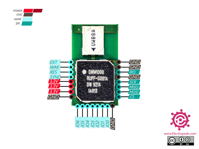
If you look at that board the SPI connections are directly from the pins to the module. The extra parts look to be LEDs on the GPIO lines and a capacitor on the power input.
So no changes to your previous design, treat this as if it was a DWM1000 with easier to get to pins.
1 Like
Hello @AndyA
When I created this question weeks ago I didn’t know anything about MOSI, MISO, SCK etc pins. Thanks to you I have a little more clarity.
In relation to my last diagram I am seeing a connection error. That is, I did not put the MOSI, MISO, SCK, etc. pins with the correct ones according to Arduino Mega (it is not the same in Arduino Nano or in Arduino UNO, as I see it). Now I do have it, I’ll show it to you because since I’m not an expert I want a 2nd opinion.
Arduino MEGA
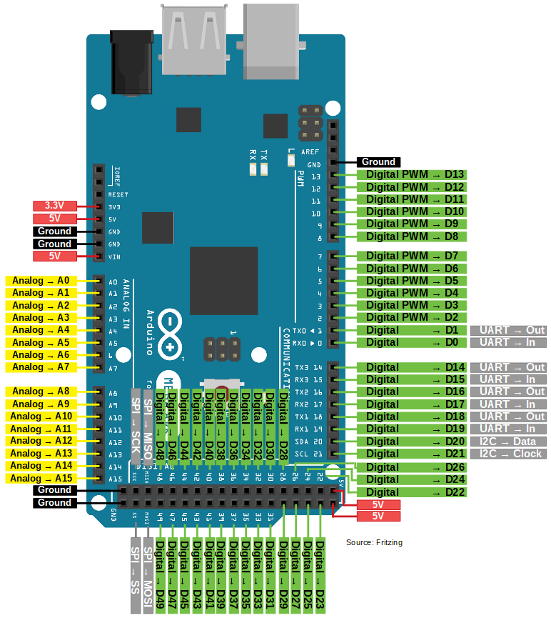
(The prines MOSI, MISO you can see below, the gray ones, below 48 and 49)
My connections are the following:
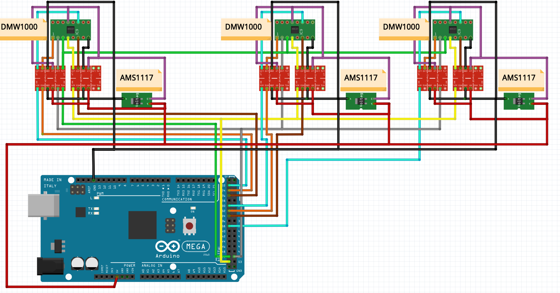
(Another error that I had was that I did not have it connected to the ground and 5v to the arduino mega)
Arduino nano

I only changed the MISO, MOSI, SCK, 5V and GND connections, everything else is the same, do you see it without errors?
I think it’s perfect now, but as I said before, I’m not an expert, what do you think?
It looks reasonable. Your pinout for the DWM1000 is a little weird in that the pin 1 on your symbol isn’t pin 1 on the module but I’m assuming that’s because of the different symbol shape. The pin order looks correct.
My only other concern is that an Arduino Mega is not exactly the fastest processor around. In fact on the scale of modern microprocessors it’s in the painfully slow category. UWB two way ranging relies on being able to respond to a UWB packet within a certain amount of time. As the decawave app notes indicate this is possible on a processor like this but you may well need to increase some timeouts from the defaults (if you’re using an arduino library this has probably already been done). If you are trying to drive 3 modules from one processor like this then you’re going to be limited to only using one of them at a time. This shouldn’t be an issue given your application.
1 Like
Don’t worry about it, just look at the order please. In the diagram I use a representation/example board for the DWM1000 module.
What do you recommend me? Use 3 arduino nano as anchor and one arduino nano as tag?
I am waiting for the DWM1000 module adapter to arrive in the next week, but if I need something else to buy, I do it, I want to work without errors or problems.
Thank you very much, you are very kind for your help, @AndyA
Don’t use Arduino ![]() I’m not a big fan of the platform, it’s ok for quick and dirty hacks but the supported platforms aren’t great and the libraries hide too much of the hardware capabilities.
I’m not a big fan of the platform, it’s ok for quick and dirty hacks but the supported platforms aren’t great and the libraries hide too much of the hardware capabilities.
Personally I’d look for a 100MHz+ Arm M3 or higher processor. Probably an STM32 since that’s what the decawave libraries and demos are written for.
But I’m guessing that would be getting even further outside our comfort zone. The parts you have will work for the use you are planning and this is part personal preference so I’d say stick to what you have for now.
1 Like
I have a Raspberry Pi 4, 8GB. Is it possible to use it? Or some alternative to only use the Raspberry, because I use Arduino only for the DWM1000 module.
Although, I need a small microprocessor to serve as a tag. The size of the anchor ones doesn’t matter much to me. I am starting, I must look for one that has open source, that’s why I chose Arduino.
I think there is an arduino with STM32, I don’t know if I’m wrong, confirm me, please.
A Raspberry Pi is certainly fast enough but because it’s running a full OS it is tricky to get the same low and repeatable response times that you can get with a microcontroller. An STM based Arduino would probably be a good option for you if you are more comfortable with Arduino than pure c / c++ code.
But as I said, I don’t think it’ll be an issue for what you are currently trying to do. It’s purely something to keep in mind if you want to re-use the basic idea for something more complex in the future or if you find you need things to run faster.
1 Like
This person uses an arduino pro mini (I understand it is less capable than nano): Wayne's Tinkering Page - UWB Ranging with the DecaWave DWM1000
Can you give me an example of uses in which more speed is necessary? Please.
Tracking lots of things or fast moving things will be the normal reasons for needing more speed. For lots of things you need faster ranging to be able to update them all in a reasonable time. For fast items you need to collect measurements quickly so that it doesn’t move too far between the ranges from each anchor.
1 Like
To avoid stressing myself with the code, speed and connections I am thinking of doing the easiest, the following: 4 arduino nano. 3 anchors, 1 tag.
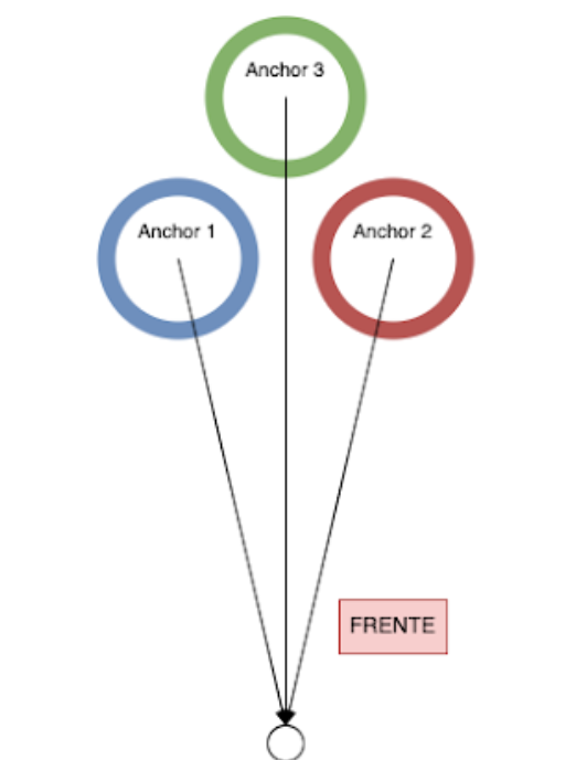
I will send the data of the 3 anchors with serial communication to Raspberry Pi, so I know the distance of the tag to triangulate the position. What matters to me at this stage is that it works. I will separate the anchors at a distance of 20 CM (like a triangle, two on each end and one on top).
Do you think it will work well?
Note: If you think I need any extra component, I will value that you tell me, so I buy it with time. Please.
That basic structure will work, the positioning process is still the same as before but you are splitting the work up more so that each individual component is simpler.
You will need some way to tell each of the 3 when it is their turn to measure the range, they need to take turns in order to avoid talking over each other. You could easily do this based on a serial message from the raspberry pi, that way it is in control of everything.
If you want to get fancy you can also get each of the 3 on the robot to measure to each other. Still use the real physical distances for calculations not the UWB measured ones. But measuring like this would allow you to sanity check the system, if the ranges are completely wrong then something on the robot may have been knocked out of position.
How will you connect it all together? Can the nano act as a USB serial port? If so that would be by far the easiest way to connect them.
Remember that raspberry pi IO pins are 3.3V so you will need a level converter to connect them together using the IO. Also serial connections are point to point so unless you get clever with the hardware connections you’d need 3 serial ports on the raspberry pi.
And one tiny nitpick - it’s trilaterate not triangulate. Triangulation is when you measure angles, trilateration is when you measure distances. This mistake is common enough that everyone will understand what you mean if you use the wrong one but using the correct term can help when searching for information online.
1 Like
I am not going to connect the pins directly to the Raspberry Pi, I plan to connect them all to a corresponding Arduino Nano, as shown in the image, and then send the data via USB serial communication (the serial communication feeds the Arduino with 5V). Raspberry Pi has 4 USB and there are 3 archos. Each port will mean an anchor.
The robot will measure the distance. The anchors will be at 20 CM, if the distance of anchor 3 is greater than anchor 1 and anchor 2 means that the tag is in front, if it is smaller it means that the tag is behind. Do you understand why I want it?
Tell me something that is still not clear to me, please:
1- If there are 3 anchors in different microcontrollers, won’t they communicate with the anchor at the same time? That is, in microseconds I first ask anchor 1 to tell me the distance of the tag, then anchor 2, and then anchor 3. Can I or can’t I do it at the same time?
2- If there are 3 anchors connected to the same microcontroller, will all 3 connect at the same time? How do I know which measurement corresponds to which? I was thinking of using this code mentioned here, but I realized that it is for case one (an anchor per microcontroller). Interfacing DWM1000 Positioning Module with Arduino
3- The tag does not need any bluetooth module or other communication, that is, the DMW1000 anchors will only read the closest DMW1000 tag module, right?
Thank you, you are right.
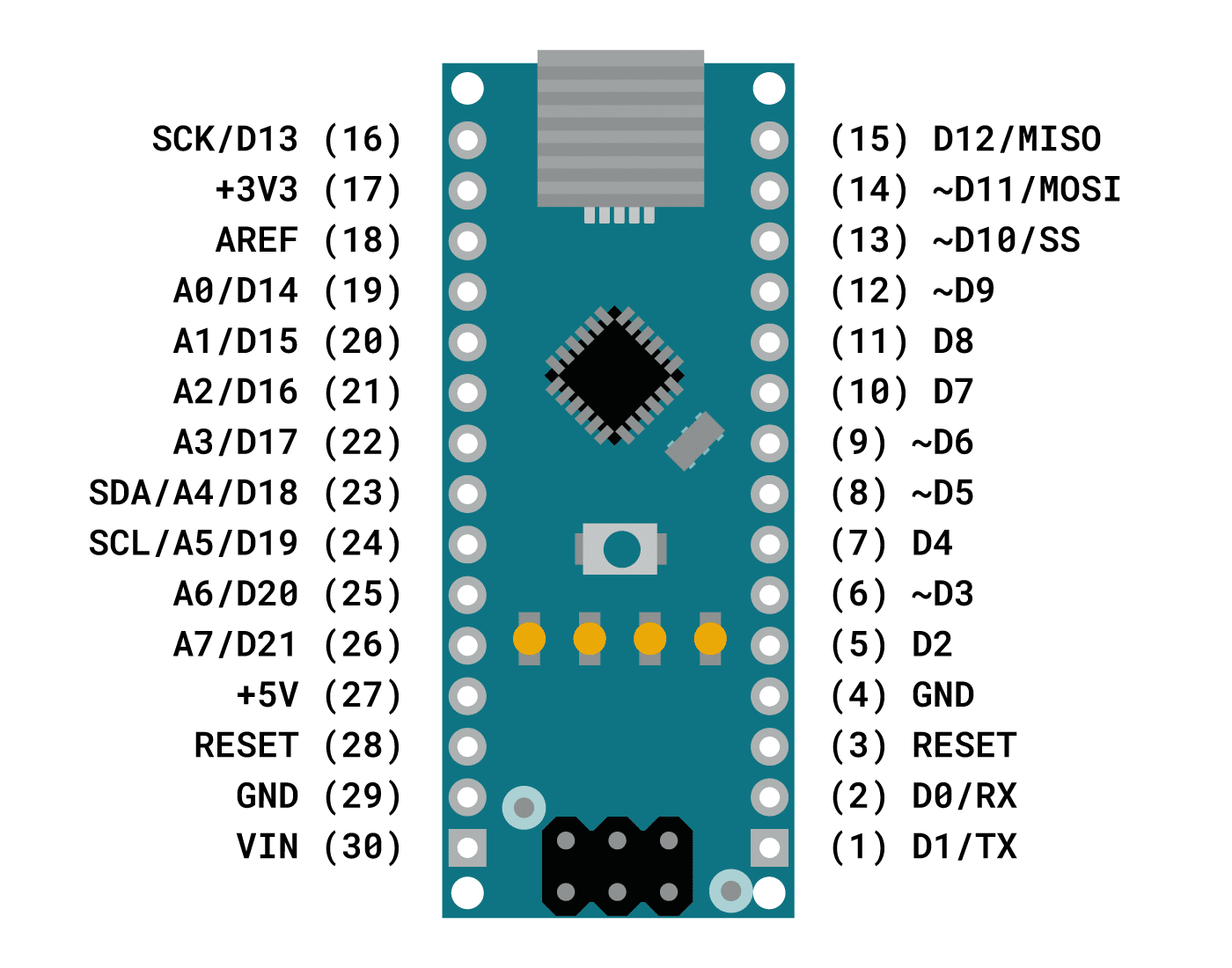
I understand that 3.3V is necessary for the DWM1000 module. That is, in this hypothetical case I do not need the logical converter. I say this because I am thinking of buying 4 arduinos whose pin output is 3.3v, so I avoid having the converters and everything is more elegant.
This Arduino:
The board operates on 3.3v logic levels but its GPIO pins have been tested to be 5v tolerant.
I see someone else did something similar https://youtu.be/-OjggUJiRbE
What do you think? Should I buy this module? Or should I just keep the nano 5v + converted to 3.3v?
You need to instruct them to make the measurements one at a time. If all 3 attempt to measure at the same time then the radio signals will combine and corrupt the message to the tag.
How you do this, the order and timing is purely up to your software.
Again, purely down to your software. They will do whatever you tell them to do. How do you know which tag / anchor pair a result is for? By keeping track of which anchor you are talking to and which tag you asked it to range to. Or by including that information in the messages.
And again, down to your firmware. You can request the range to a tag with a specified ID or to any tag that hears the message. Of you could use bluetooth to tell a specific tag to reply rather than including the ID in the UWB message. There are lots of possible ways to do this. Generally you want some way to specify which tag you are talking to, otherwise if there are two tags in range they will both reply at the same time and the replies could corrupt each other. Including this in the UWB message used to start the range measurement is normally the simplest way to do this.
Getting only the closest to reply would imply the tags already know their range to the anchor and the range to the anchor of all the other tags in the area before any ranges have been measured. If you can figure out how to do this then that would be impressive ![]()
If you don’t have any hardware yet then yes, using something that has 3.3V IO makes life easier. But if you already have the parts then a level shifter isn’t that big of an issue. There are hundreds of different ways to build something to do what you are aiming for. All of them have different pros and cons. You need to just pick one and go with it.
Generally I’d say use the parts you have already unless they are unsuitable. If you need to get new parts then pick the parts you are most familiar with unless they make things needlessly complicated. And once you make a decision stick to it unless you find an insurmountable issue with it. Don’t get half way and then decide to go a different route and start again unless you have no choice. That’s the way to end up with a dozen partly working prototypes and no end solution.
1 Like
You’re right. That advice is worth your weight in gold. Thank you.
Honestly, my level is still a bit basic, I’m going to try with 3 anchors and 1 tag separately… and then I’ll see how to solve the problem of having two different robots so that the DMW1000 modules are not mixed.
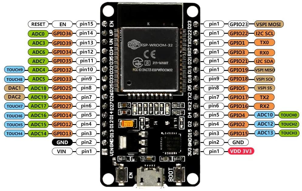
Look at this microcontroller (ESP32), it has bluetooth and its logic pins are 3.3V. These are a good option because they are famous, they work with arduino and I think they are faster than an Arduino UNO/Nano:
https://www.amazon.com/-/es/desarrollo-desensamblado-nodeMCU-32S-microcontrolador-procesador/dp/B08DQQ8CBP/
(Bluetooth is useless now, but, as I am experimenting in the future, I can use it to call a single DMW1000 when there are many.)
I ordered 5 arduino nano, but I am going to cancel that order and make the new order, confirm me if ESP32 is a better option, please.
Excuse the indecision, I’m learning as I go.
I’ve not done a lot with ESP32s but yes, they have a lot more processing power than a nano.
I would check if there is a working DW1000 library and examples available for them, having to port the drivers/library over yourself would add a lot of work. I expect someone has done this but with this sort of thing I find there is a huge variation in quality, but how well it’s been done and how well documented it is can make a huge difference.
Start with one anchor to one tag. Once that works try 3 anchors to 1 tag. Then 3 anchors to 2 tags (measure one tag and then the other).
Only once you’ve got that working look at 2 robots. This should be much the same as 3 anchors 2 tags but with a different set of 3 anchors for each tag. You could either use the Bluetooth or wifi to communicate between the robots as to who’s turn it is or have them passively listen for the other ones UWB packets to work out when the other one has finished.
1 Like
ESP32 runs Arduino, that is, it is the same library.
These use an ESP32 module integrated with DW1000. Apparently it works fine:
I’m going to buy it for testing.
Here I made a diagram for the ESP32:
GPIO5: SS - Orange
GPIO23: MOSI - Gray
GPIO19: MISO - Green
GPIO18: SCK - Yellow
GPIO13: IRQ - Brown
GPIO12: RES - Cyan (Blue)
GND: GND - Black
3.3V: 3.3V - Purple

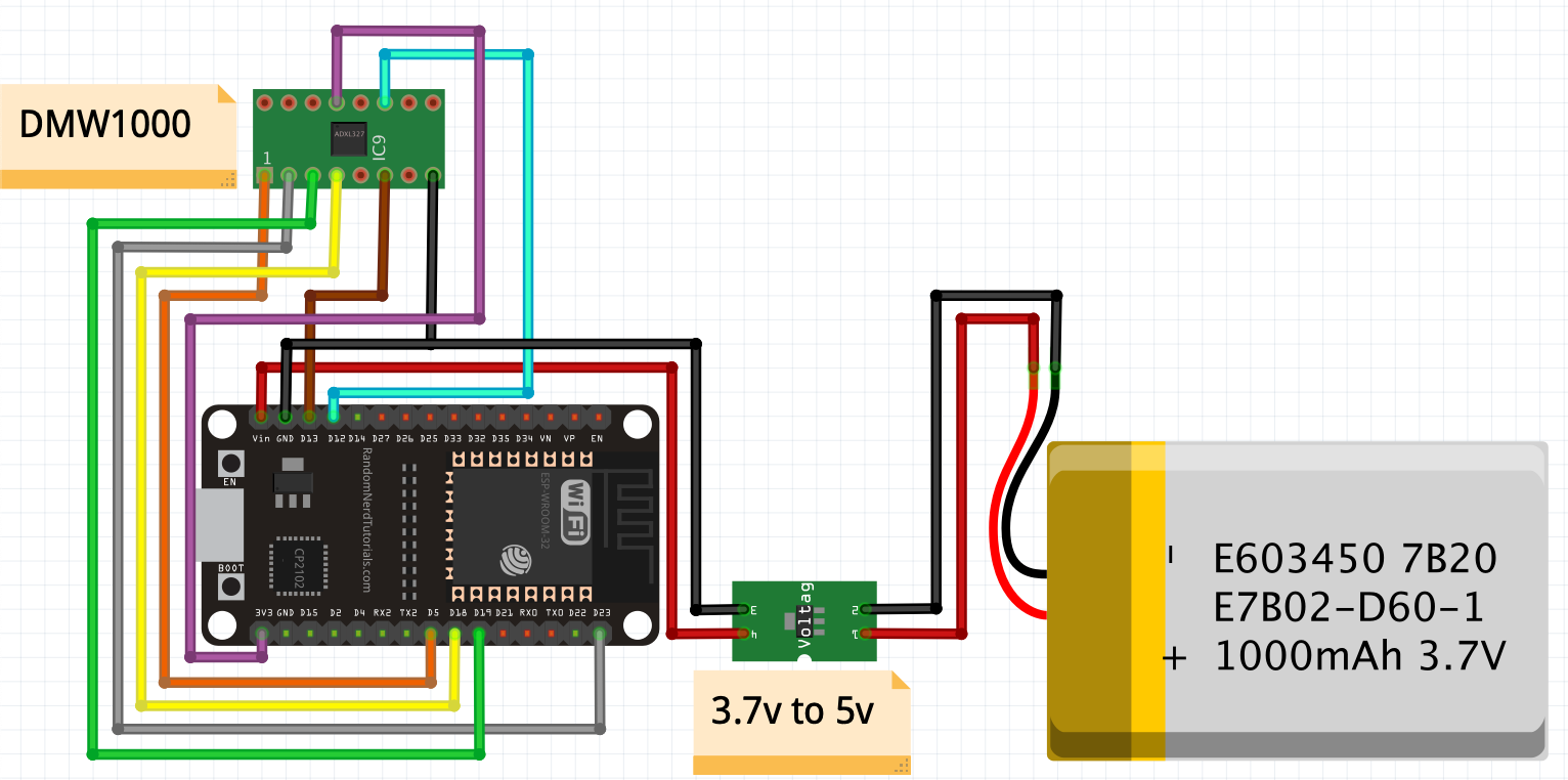
Remember that the power will be via serial for the anchors, only the TAG will be with a battery and a 5V voltage regulator.
Do you see any errors? I think it’s ok, I just have doubts about the GPIO13 and GPIO12 pins.
I’d forgotten that arduino works on that part, when I used it the code was c++.
I have found some mention that GPIO12 is a bootstrap pin on that board and need to be low to boot.
So maybe avoid that one for that reason.
Same for GPIO 5, that needs to be high to boot.
Since the library probably doesn’t care which pin you use for select or IRQ I’d move them just to play safe. It’s probably not an issue but why take the risk  13,14,27,26,25,33,32 all look to be OK to use as do the MOSI, MISO and CLK pins you’ve used.
Beyond the pin changes above just to play safe I can’t see any obvious issues with the connections.
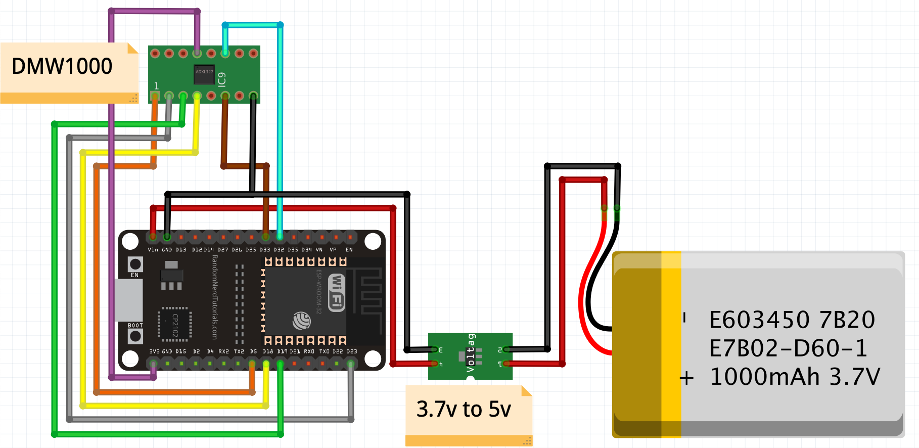
I moved the pins to GPIO33 and GPIO32.
GPIO33: IRQ - Brown
GPIO32: RES - Cyan (Blue)
Can I use power with 5V? I didn’t see any reference to it.
Thanks a lot. When everything arrives and I try it, I will keep you updated.
Yes. My guess is that they have a simple LDO to regulate the voltage down to 3.3V so the exact input voltage isn’t too critical. If it is designed to also run from USB then anything 4.5 to 5.5 will be fine.
1 Like