Is it possible to simulate and get exact outputs when a circuit has 2 different grounds, if so how to do that?
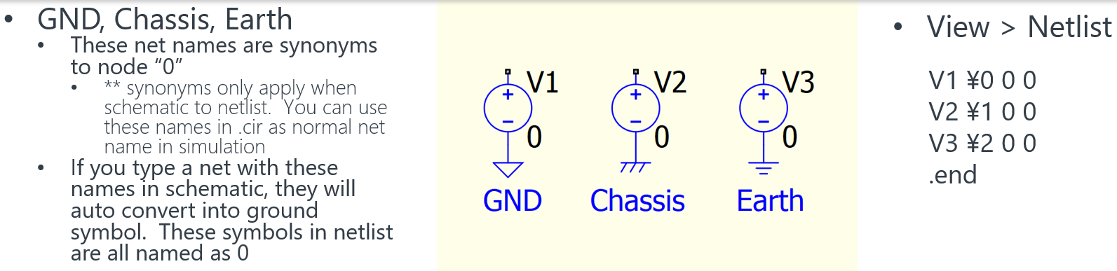
Ground in spice simulation is node with voltage defined as 0V potential. When you probe a node, it is voltage different between that node and 0V node. All ground symbols in Qspice is actually same, a 0 node in netlist.
Can you be more specify what you are referring to 2 different grounds? Any schematic as reference?
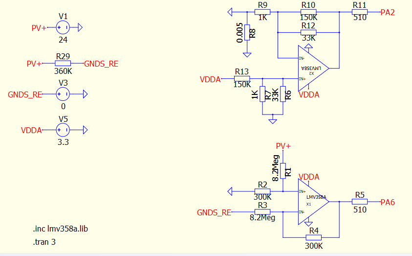
@zrtn yes, no problem, you can use as many distinct reference points for fake “GND”, for example for a power supply with multiple secondary outputs, all of them separated and fully isolated from the primary side. You have to follow a few guidelines:
- Do not use the node 0 (zero) from SPICE to associate an isolated “ground” to the main GND
- Use distinct net names, like GNDS_RETURN, +5VRET, -15V_RET for example
- As it is absolutely the case in real life, use some big resistors and small capacitors connecting these floating and isolated reference points to the primary side, main GND
- Remember, you MUST ALWAYS measure now in a differential mode the output voltage, it is not anymore referenced to GND
2 Likes
Do you have any example circuit which has isolated grounds and how to measure when using isolated grounds
Can you tell us more about your circuit?whats that?
why it needs isolation in simulation?
*I have no question about real circuit isolation
If you have isolation, i.e. optocoupler, transformer, isolation chip, or whatever.
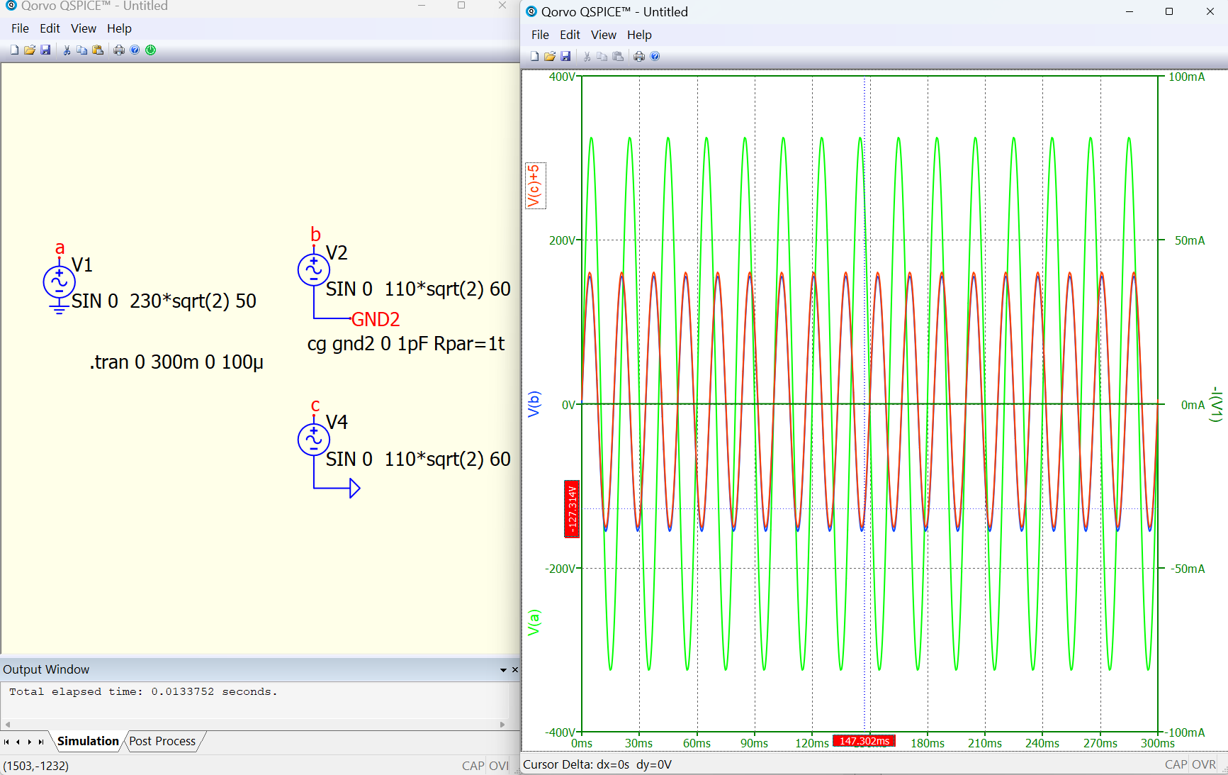
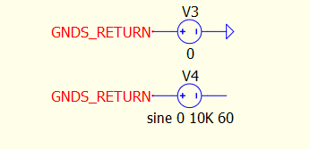
Simply tie a V source between the input ground and the isolated ground.
Set the V source to 0 volts and the the isolated ground will now be at the same potential as the input ground, but you are still isolated.
If you get current through the V source, you’re isolation is no good.
When you are ready to test the isolation itself, simply set the V source to 10KV at 60Hz and watch for AC current through the V source. If you have current your isolation has failed.
Easy peasy.
All for now
1 Like
How to test the isolation, is it the same voltage source i need to change from 0 to 10kv
Hello @zrtn
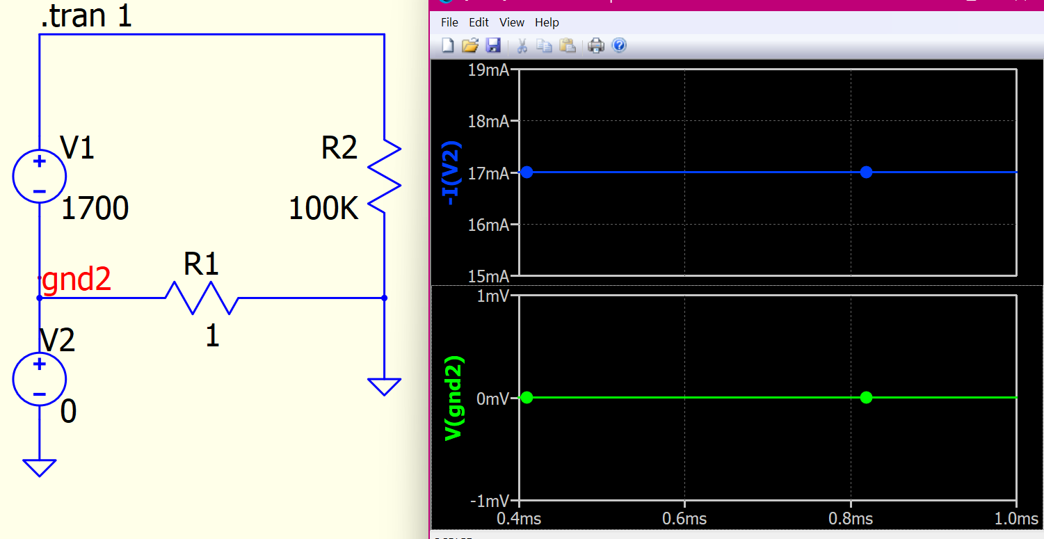
Im getting current flow through the voltage source, someone explain me, thanks.
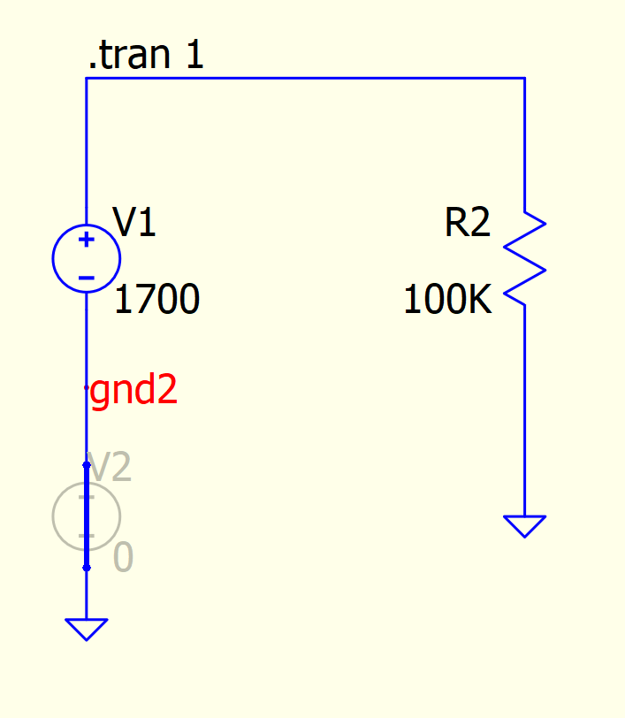
Because you must provide current to “hold” that net at 0v without the current that net will not be 0V (unless you ground it, see example 3):
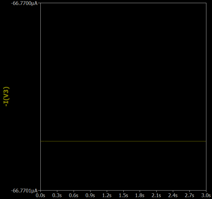
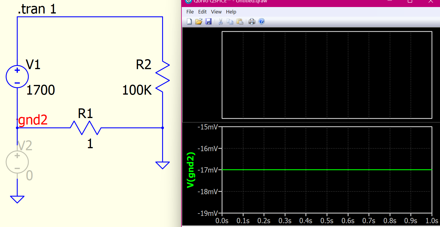
remove the current source (now i(v2) is unknown so not plotted, current loop through r1)
short the current source (the current loop passes through common ground, not R1)
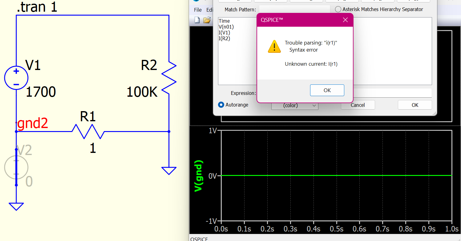
well that should be obvious by, v=ir if v=0 i will be 0, kind of surprised that throws an error but it is the same circuit as:
So how can we create proper isolated ground?
Do you even know what are you doing?
Why need isolation in simulation?
In simulation environment, real isolation is not exist. as in the case of real hardware.
Between two isolated things, there must be some capacitance albeit tiny (femto-atto Farad) and very big resistance in the order of 10s of Mega to Tera ohm.
Additionally, in Spice circuit is often not as simple it appears. various RLC are added everywhere in the background to improve numerical stability aiding convergence.
Arief.
Based on your statement 2, then we need to add also the following question to your first above question 1 (“Why we need isolation in simulation?”) is as follow: Why we need isolation in real hardware?, as real isolation not exists in both simulation and real hardware (based on your above statment number 2)
Also, If real isolation not exists in both simulation enviroment and real hardware, then why people are discussing about isolation, and how to isolated two or more things one from another? Its fake isolation? Or how to understand isolation in both simulation enviroment and real hardware? If someone can explain the real meaning of isolation
And also the “isolated” signal is referencing in the end to 0V/GND?
Its not productive to go down the rabbit hole on the definition.
Anyway I can tell you for sure that I never need to create isolation in Simulation.
I can put 3.3V logic circuit on the same ground with 1MV circuit without any isolation whatsoever in simulation. All isolated power supply that I am aware of are simulated with common ground
2 Likes