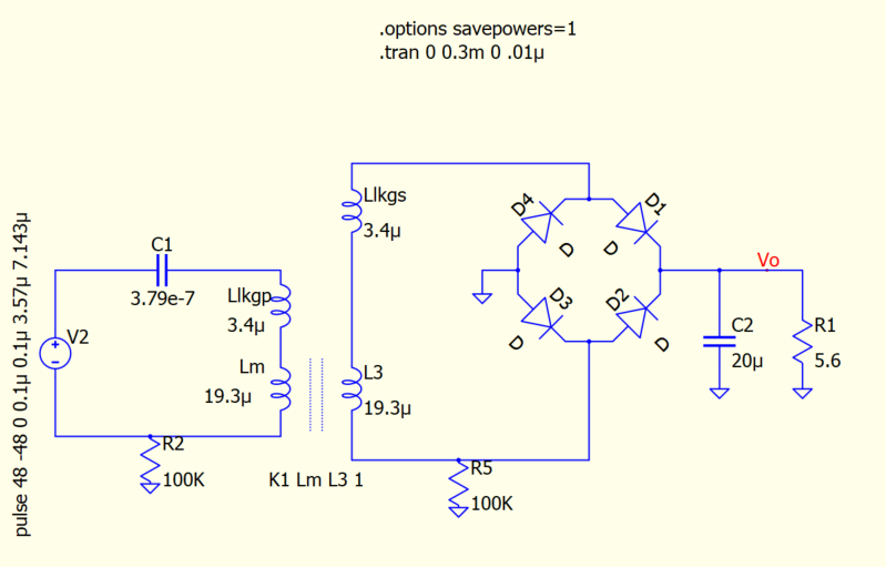
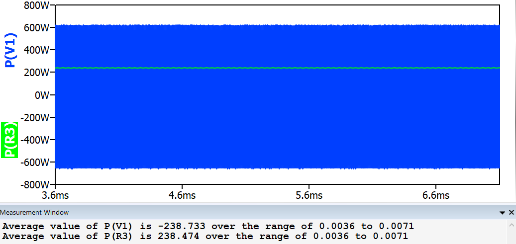
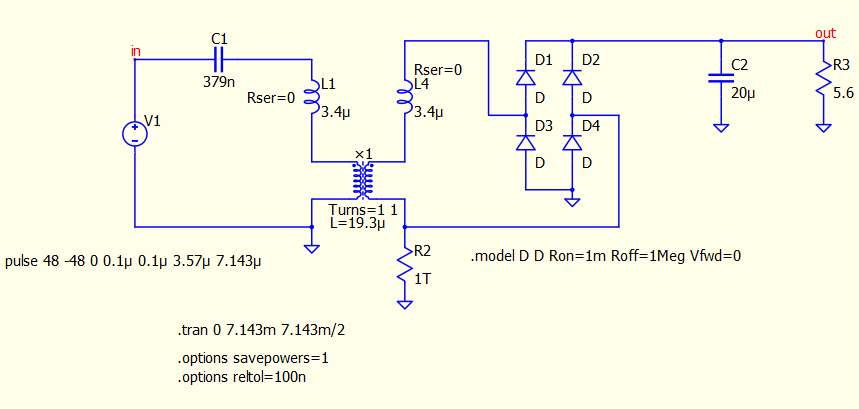
I created a sch of a circuit with a coupled inductor and I was trying to analyse the efficiency of the system. To my surprise, the power in the input source does not match the power in the load:
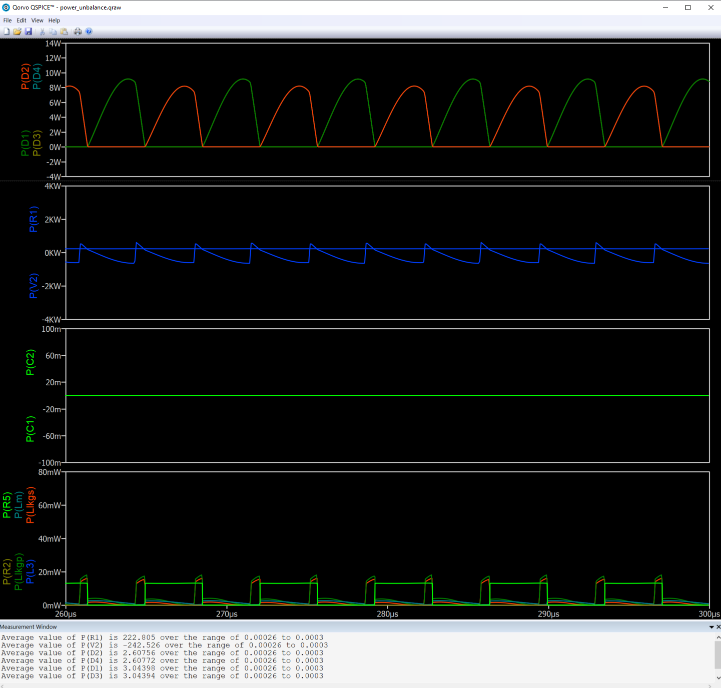
Ivan, yes, the diodes are dissipating power as shown in the simulation results where the average power dissipation is calculated for components. There’s a difference of 10W between input and load + rectifier.
@mosfet you cannot calculate the power the same way like a DC source and a few resistors. What you are dealing with here is an AC source with inductors, resistors, capacitors, and phase shift. Some reactive components are forced to charge/discharge with different delays, and even if you did not specified parasitic ESR and winding resistivity for these reactive components (charge/discharge with zero losses) you have other resistive elements eating power at any moment, regardless of the phase shift. You have to also take into account the phase shift (delay).
As per my understanding, as long as the energy in the reactive components do not change between cycles, i.e. pk voltage and current in caps and inductors, respectively, even though the reactive components take and return energy, the net after multiple cycles should be 0.
You mentioned other resistive components dissipating power, could you specify which?
I didnt follow the phase shift stuff so maybe that’s what I’m missing. Do you mean phase shift between voltage and current as would happen in an impedance which is not purely reactive? For an RL load for example the net energy in the L after N cycles in steady state should have an average of 0 with an AC source.
@mosfet, first the phase shift. Yes, you need to take into account the phase shift, but not “locally” as you see it looking at one inductor or capacitor. You need to consider the phase shift as it is propagating all over, in the whole circuit.
Then, about “other resistive components dissipating power”, I suspect you missed R2 and R5. It does not look like these are dissipating something, especially if you do not have parasitic stuff defined for your components. But, if you defined some capacitive parameters for your transformer windings for example, the story changes. The fastest way to verify, in your specific schematic, is to check the power on these resistors. Are the multiple and isolated ground points bouncing with respect to each other? Then yes, you will dissipate some power in R2 and R5.