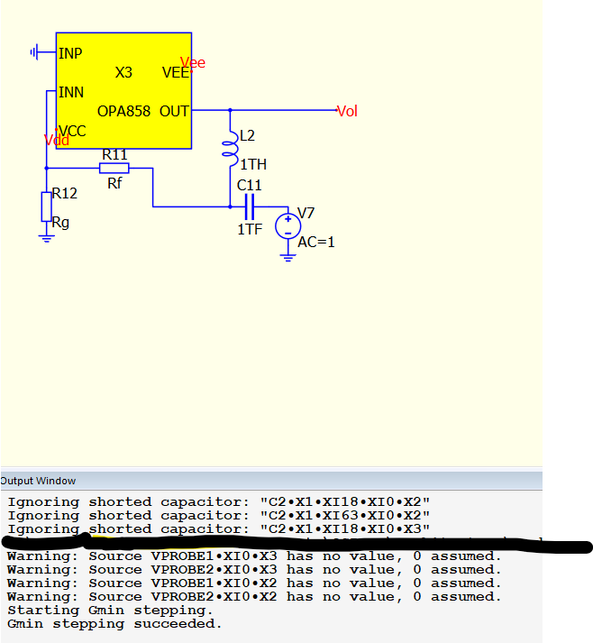
within my schematic as shown below i imported the Spice symbol with multiple subckt’s I included the entire file. though while simulationg it shows the following erros/warnings.
and the schematic which has a ±5V supply, or 2.5VCC and -2.5VEE. in simulations it seems rather okay, but while doing the openloop gain simulation, the gain is lowered by 6dB which is not expected.
This error, raises questions about the warnings and other errors i’m receiving, does anyone know if this is a reocurring problem while importing PSpice or Spice files from TI?
the spice is downloaded from TI’s website. i cannot upload any files to this topic.
Kindly would hear from you all, if there are any questions or other problems.
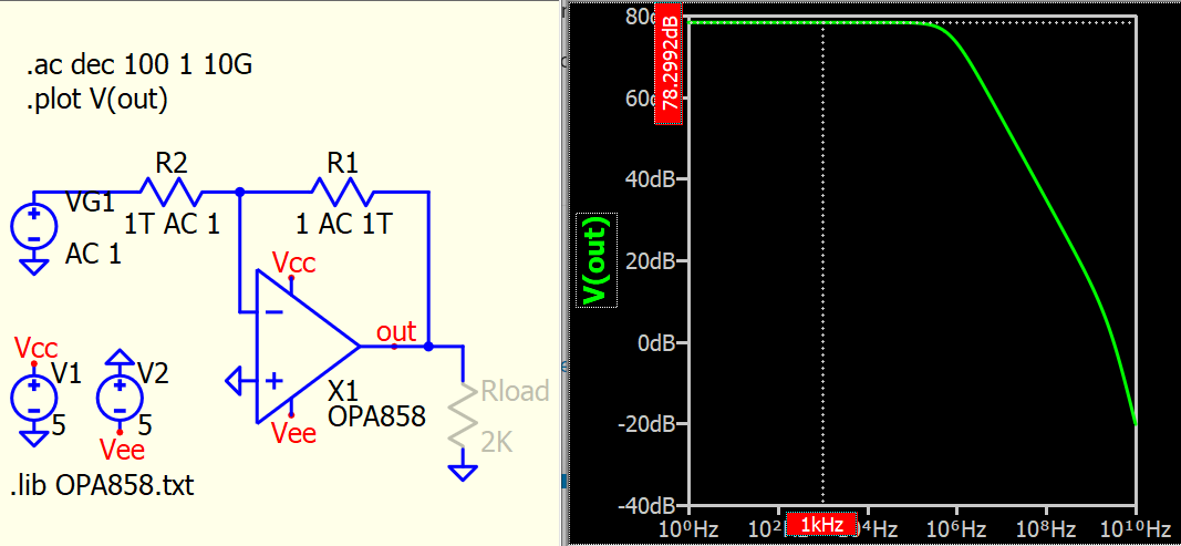
This is open-loop gain test circuit according to Mike’s article (An Op-Ed on Op-Amp Modeling - Qorvo)
You said gain is lowered by 6dB, where you refer to? You expect simulation result should be 84dB? Where is the reference that AOL is 84dB?
Hey KSKelvin,
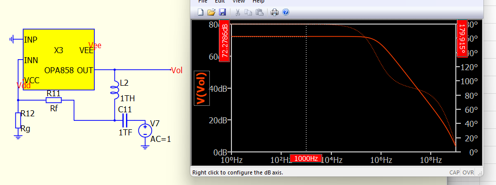
My output of the Vout or AOL is 72dB, i expect this to be below the 80dB point as stated in the datasheet by TI. Is this due to the feedback that i have implemented in my circuit, or due to the errors and warnings it is giving me?
I am also noting that your Aol simulation is rather different then mine. Though it is rather similar, in the fact that im using Inductors and Capacitors for the role of the switching.
However, my question truly is sorry if i misspronounced it is, would the short circuiting capacitances be of any problem threat to the believability of the simulations?
Though, thanks for the quick reply and the new knowledge gained by the article reference.
Mike’s article use the ideal that defines different resistance for .op and .ac.
In .ac, R2 is 1ohm and R1 is 1Tohms, which force the amplifier gain as large as possible and therefore, result is opamp open-loop gain.
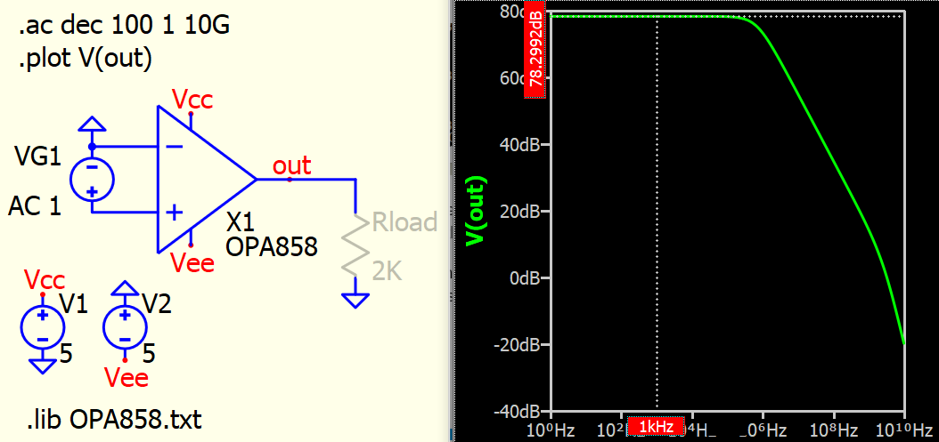
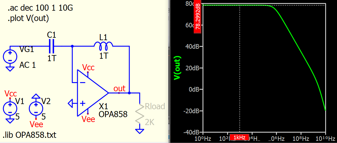
Here is another circuit that can also test the open-loop gain.
In your setup, why you add R11 and R12?.. that may be the reason you got some attenuation.
I just include 1T capacitor and 1T inductor and can get same open loop gain likes above two cases.
first off, i did not know there where that many possibilities of simulation open loop gains.
What im attempting to perform is the stability analysis with Rate of Closure(RoC), and phase margin.
For RoC, i need to be able to define the open-loopgain, with the 1 over beta coefficient. though your simulation gives a beta of 0 as the Inductor is closed i think, correct me if i am wrong.
So that’s why I implemented the R11 and R12, and yes weirdly enough they are the reason for the attenuation of 6dBish. A co-student told me it would be fine to keep them in the loop as it should result in the correct open-loop gain.