we are developing design using DW1000.In that, we need to calibrate our custom board as CE/FCC. we sent our board for FCC/CE testing.when i got test Report , RF testing is failed.
kindly check my test report and Give me the feedback of the report
TEST REPORT RESULT
CE标准条款:EN302065 标准限值:
FCC标准条款:Part 15H
标准限值:
不合格数据:
190 2 1
深圳市宝安区福永街道重庆路 号卓科科技园 栋 楼
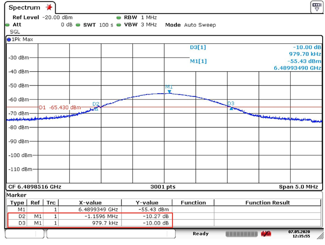
EN302065标准规定在样机在允许工作的频率段中发射信号的
带宽必须大于50MHz,由上图可知样机的-10dBm带宽
BW=1.1596MHz+0.9797MHz=2.1393MHz,测试结果小于50MHz,因此该测试项Fail。
FCC Part 15H标准规定在样机在允许工作的频率段中发射信
号的带宽必须大于500MHz。参照CE的测试结果,样机发射信号带宽也是不满足FCC的测试要求的。
Pertinent translation of the Chinese part (via Google translate, I don’t know Chinese, sadly):
You don’t give much to go on, but here are the things that stand out:
FCC part 15 subpart H isn’t about ultra wideband operation. You either want to be under FCC part 15 subpart C 15.250 or subpart F 15.517 or 15.519 depending on your use case. Given the channel 5 frequency, most choose 15.250 since the rules are somewhat more flexible and simpler than subpart F.
In all of the above rules, the requirement is the the -10 dB bandwidth be 50 MHz or larger. You have to generate a signal that is spread over a large bandwidth. This image shows a very narrow spectrum.
Given that the spectrum analyzer resolution bandwidth (RBW) is 1 MHz and the plot is only 5 MHz wide, this looks like a CW signal right on carrier frequency that has been rounded by the RBW. Your indicated bandwidth of 2 MHz for -10 dB down is consistent with a 1 MHz RBW at -3 dB down. If the lab sets the RBW tighter, say 1 KHz, I bet this turns into a sharp spike at Fc.
In other words, I think your test article is misconfigured and producing a CW signal instead of an UWB signal, and a weak one at that. This could be due to other misconfigurations that are preventing the wideband modulation from occurring.
Do the devices actually work to send UWB signals? I bet they don’t when programmed as shown here. The general approach is to get the device working (making proper UWB signals) and then gratuitously saturate the transmit duty cycle to speed up testing for the lab since most UWB devices have very low duty cycles.
Mike Ciholas, President, Ciholas, Inc
3700 Bell Road, Newburgh, IN 47630 USA mikec@ciholas.com
+1 812 962 9408
Hi ,
I forwarded to your reply to my testing team.
I got reply from testing team
As for the test standard, we will re-evaluate it internally, but no matter which chapter is used for the test, the prototype does not meet the limit requirement( −10 dB bandwidth of the fundamental emission shall be at least 50 MHz).
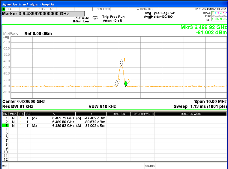
According to the your project description, we have re-captured the spectrum diagram. We used the largest RBW VBW of the spectrum analyzer and set a wider Span, so it can be seen that the transmission bandwidth of the prototype is still very small (6496.5mhz-6483.5mhz =13MHz).
I understand that the duty cycle of UWB function in the customer’s engineering description is very small, so when we grabbed the picture, Max held for about ten minutes, and there was no obvious change in the result.
If you set your device to constantly transmit then you should be able to see the signal.
If you set it to the carrier only test mode then this is easy to see, a cheap SDR connected to a PC will be able to pick it up (although generally those will only be able to get channels 1-4, they don’t normally go high enough frequency for channels 5 or more).
To pick up the actual signal or higher channels you will probably need a real spectrum analyzer.
i had sent two custom board(DW1000) for CE testing again.
First one was continuous wave code from api.(unmodulated)
Second one was Simple TX .(modulated wave)
I got a report from Testing Team(continuous wave ie unmodulated wave).
In Modulated signal(simple tx), it didnt emit signal.
i have a question on modulated signal, in which example should i send for CE/FCC certificarion.
kindly help me . thanks in advance
For the modulated signal you should first work out what your worst case output is.
Do you have any packets that last over 1ms? If so loop outputting this constantly.
Do you ever output two packets within the same 1 ms period? If not then output your largest packet once per ms.
If you output more than 1 packet in 1 ms then work out your worst case for maximum transmissions and output that in a loop every ms.
The test lab will need to know that this is a UWB system they are testing and will need to follow the appropriate test setup, it requires different equipment settings from the normal ones they use for other transmitters.
I can’t help you, it’s too dependent on your code and how your system works.
Look at the radio protocol you are using, work out your worst case, set the system to constantly do that.
This is the sort of thing you should have had ready before sending anything to the test lab, ideally before you even contacted a test lab. But it’s also the sort of thing that the test lab should have told you about when you first told them you wanted to do UWB testing.
The other thing to do is ensure they are using a spectrum analyzer with a 50 MHz resolution bandwidth, they are rare. The standard allows you to use a lower bandwidth setting and then apply a formula to adjust the result but unless your spectrum is perfectly flat that won’t work as well and you will end up with a lower transmit power than you want.
Had given default Tx power which s n Simple TX.
what should i do to reduce the peak emission?
Is it possible to do in API side ? If its so, let me know the way.
Thanks