Good morning,
my name is Gianni, 68yo engineer with hobbies in the informatic/communication/navigation environments but real beginner in using the DECAWAVE products.
I’ve setup a test bed using a single anchor and switching across 5 tags.
Tags have been replaced in the same position and anchor was not moved.
I used Hyperterminal to record data taken from the tags with the command.
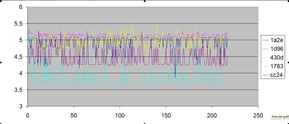
I expected to get similar results. Instead attached you’d see the outputs.
First observation: two of the sereis appear very stable but the other three are very noisy.
Second: The noisy series have a relatively flat reference but suffer high spikes
Third: there is a huge difference among the measurements.
Real distance is 341 cm.
What am I doing wrong?
NOTES
The system was positioned at the two opposite sides of my table in los conditions but with my portable PC on the table.
The DWM1001-dev boards have been bought all together from digikey immediately before Christmass 2018.
When placing the tags in the same location are they also in the same orientation?
Do you have a direct line of sight between the tag and the anchor antennas?
The flat base line with upward spikes is what you would expect to see when the direct path is weak due to range or some attenuating obstruction. Some of the time the direct path is correctly detected and you get the correct distance, some of the time the direct path leading edge isn’t detected due to the signal being too weak and either the direct signal is measured late (at the peak not the leading edge) or a multipath distance is measured instead.
If things are relatively static you can use this to your advantage, you will always measure the correct distance or more so if things are static, never** less than the correct number. So 1) collect a set of ranges, 2) discard any more than 20 cm greater than the minimum (assume a +/- 10cm noise level) 3) average the remaining measurements.
On your 3rd point, this looks like the antenna delay needs calibration on the units. Each unit will have a very slightly different delay on the antenna. The ~1.4 m variation you are seeing is a little larger range that I would expect this to cause but would certainly explain some of it it you haven’t taken this into account. The application notes give details on how to calibrate this.
** OK it is possible to measure significantly less than the correct distance but it takes some odd situations. I’ve seen it twice, once in a building with 300 sq m metal walls at both ends and once when set up directly in the path of a powerful microwave link.
Hi Andy,
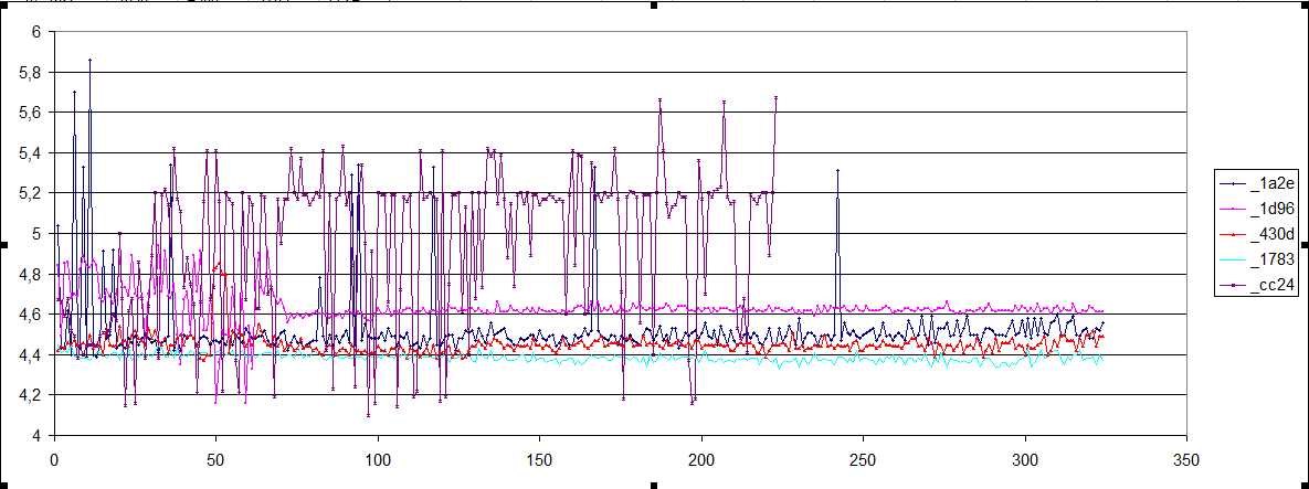
I’ve repeated the test in a different site. The results are significantly different.
Now four of the tracks are close to the real value of 4.5m.
Anyway the CC24 track is significantly different and noisy.
The previous tes was run from one side of the room to the other. Two walls were parallel to the path, thus causing possible reflections.
In this last test, the two devices were placed in two opposite corners, thus reflections should be minimised and much less spikes were measured.
The initial 75 samples were noisy for all the units.
The boards were placed with the antennas vertically oriented and whit the pcb’s aligned on the same directions.
I wait suggestions based on your experience.
Many thanks, Gianni
JUST TO NOTE unit CC24 continue to exhibit poor stability. Is it worth the case to reload FW or make any additional operation? should I send it for check to any lab or decawave support center?
That is looking a lot more like the variation I’d expect to see due to antenna calibration issues, on the units I have here I normally expect a ~20 cm range before calibration.
Generally if the direct line isn’t blocked reflections aren’t an issue, I’ve run systems parallel to wetal walls without seeing anything odd, that is the big advantage of UWB. It seems a odd that moving the location in the room had such a big effect. Clearly there is something going on but I have no idea what it could be.
On CC24 all I can think of is a good visual inspection of the antenna signal path to the IC. I’ve no experience with the DWM1001 so I can’t comment on issues that are directly related to it. I started with a DWM1000 and custom firmware and rapidly moved to custom hardware too, the modules didn’t quite work for my application.
Hopefully someone with some more direct experience of the modules will be able to help more.