According to the datasheet (Section 1.7), the IRQ pin should be pulled up because the DWM 1000 drives the logic level to low to signal an interrupt. Remove the 1k resistor and set an internal pull-up on the Arduino pin connected to the IRQ pin. Use the INPUT_PULLUP keyword when setting the pinmode (see https://www.arduino.cc/reference/en/language/functions/digital-io/pinmode/).
Hi Snyderitis~
Thank you for your reply.
I am doing like you said, it seem to be better.
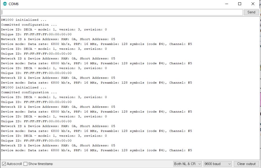
And now I got this information from DWM1000. May you tell me it work correctly or not?
Hi snyderitis ~
Thank you~ my friends.
As my post, Until now I just tried to do like the link I posted. Most of my work, I used the library from that link. I am new for DWM, So, I just did the BasicConnectivityTest example for get ID, set Network ID, and set address. I did not try to listen for packets or configure the tag. Do you have or know any good document for DWM1000?
Thank you so much for your help.
Best safety to you.
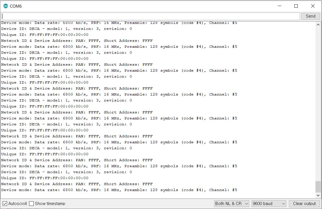
It looks like the tag is not being configured correctly. The BasicConnectivityTest should change the network ID and address. Could you post your schematics and how you’ve connected everything? It may be that the communication bus is not connected properly.
With arduino Due, I use SPI with 3 PINs for select slave. For configuring a Tag or anchor, I think I just try to do and modify program on the above link. For example, DWM1000Ranging_TAG will configure DWM1000 as the tag.
Yes~ thank you for your enthusiastic support. I am new for UWB, so many thing I have to learn about it.
If I have some problems in the future, please give me some time ^^.
And I hope you will receive many supports from your life.
Hi snyderitis ~
Until now, I removed resistor (1k) for pull-down like you said.
I tried to send data, it worked well.
But I attempted to receive data, and it could not get nothing.
I used arduino due for sending data, and arduino promini for receiving data. And I checked again external interrupt pin on arduino pro mini, it is right. So, I did not know why.
Do you know any reason for that?
One issue on your schematic - The DWM1000 reset pin shouldn’t ever be driven high.
It should be driven low by an open drain driver but should never be actively driven high since this could cause a conflict. The DW1000 chip itself can sometimes pull reset low.
One other common issue I’ve seen when people are putting together systems like this, if the SPI lines are too long or messy then you can get unreliable communications. That SPI bus is running fairly fast and is only using standard logic level drivers, it is all too easy to break it if you’re not careful with the connections.
I don’t think either of those are the issue your seeing right now (sorry, no experience with the arduino library so I don’t know what you should or shouldn’t be expecting to see on the output) but they are things to watch out for.
Hi AndyA~
Thank you for your information.
I will consider your advice
I am testing by using arduino pro mini+ dwm1000 for sender, and arduino due+dwm1000 for receiver. sender worked well I think, but for receiver from arduino monitor I got “Error receiving message”.
Do you think this problem is from SPI clock? because I see that DWM1000 maximum clock is 20MHZ, arduino due is 84MHZ.
Thanks for your time.
The nice thing about SPI is that you can always run it lower than the maximum. The lower limit on the rate is purely how long you want communications to the device to take.
It’s normally best to start a bit away from the maximum and get things working without pushing the limits first. Then once that’s working speed things up until it breaks and back off a little bit.
e.g. I had one design with a 2" ribbon cable connecting the CPU to the DW1000. I got that working at 1 MHz, and then kept changing the speed until I found it could run reliably at 18 MHz but it fell over at 20 MHz. So for that hardware I ended up running the SPI bus at 15 MHz.
Lowering the rate won’t fix all the possible SPI issues, some noise or reflection issues that result in glitches could still be there with a lower the rate. If you find you have intermittent or unreliable communications and suspect the SPI link then adding 20-30 ohm series resistors on each line next to the driving device (Arduino for everything other than the MISO line) combined with a lower speed will normally clear just about anything up. Or use shorter / neater connections
Hi AndyA
Hello Friends.
Thank you for your time
For reset pin on DWM1000, as my schematic, in my program, reset pin never be driver high. Sometimes, it is low in output mode, and almost times, I use as Input mode (leave floating).
When I tried to test as I said before (sender and receiver). sender worked well, but receiver on arduino Due (arm chip) did not work. I read SYS_STATUS and SYS_MASK registers, then CLKPLL_LL
bit and MCPLLLL bit equal 0, never set to 1. So, IRQ interrupt could not generate an interrupt. Do you know why is that problem, how can I fix it?
I also changed speed of SPI, but receiver still did not work.