DWM1001 Non-PANS questions (accuracy, factory calibrated antenna delay etc.)

Hi.
I have recently bought the MDEK1001 kit and is looking into developing a custom firmware for the modules to support our current project.
The main reason for getting the MDEK1001 kit was the factory calibration of the antennas, supposedly stored as part of the OTP.

To have full flexibility I want to avoid using the PANS library although I am aware that the antenna calibration requires us to use the same network configuration.
That leads me to my first question:
What is the network configuration used by PANS and compatible with the factory antenna calibration stored in the OTP?
Is it the one shown in Table 1 of the DWM1001 System Overview document?

With one of the DWM1001-DEV boards I have read out the antenna delay from the OTP during SPI slow-speed (right after dwt_initialise(DWT_LOADUCODE)) using the following code:

uint32_t ant_delay;
dwt_otpread(0x01c, &ant_delay, 1);

This gave me the following value: 0x404C404C
Is the factory calibrated antenna delay equal for both TX and RX? And in this case it seems to also be equal in PRF 64 and PRF 16 mode??

Unortunately applying this antenna delay in the DWM1001 examples did not help with the ranging.
Why am I observing a 25-30 cm distance bias/error when the factory calibrated antenna delay is used? This appears independent of whether the TX/RX preamble code is set to 10 or 9 (see other question below).

I have previously worked with the DWM1000 and are thus familiar with the DWM1000 and DWS1000 examples. For the DWM1001-DEV module I was however looking into the following examples: https://github.com/Decawave/dwm1001-examples
Looking at these examples and comparing them with the ex_06a_ss_twr_init and ex_06b_ss_twr_resp from the DWS1000 examples I don’t understand why several parameters are different:

  • Why is Channel 5 being used in the DWM1001 examples while Channel 2 is used in the DWS1000 examples? This does however align with Table 1 (as mentioned above).
  • Why is the TX/RX preamble code 10 used in the DWM1001 examples instead of 9 which used in the DWS1000? In this case Table 1 (as mentioned above) defines it to be 9!
  • Why is the RX timeout set to the maximum (65 ms) instead of an actual/expected microsecond-ranged value?
  • Why is POLL_TX_TO_RESP_RX_DLY_UUS set to 100 us in the DWM1001 example and to 140 us in the DWS1000 example? In general, why is this value set so low, given that POLL_RX_TO_RESP_TX_DLY_UUS is already larger than this (330 us in DWS1000 example, 1100 us in DWM1001 example)? Shouldn’t this delay of the response (in the responder) be accounted for in the transmitter? Or at the very least be accounted for in RESP_RX_TIMEOUT_UUS which in the DWS1000 example is only 210 us?
  • Why don’t you have any responder example with interrupt? I would expect the responder to be the most time-critical application given that the response transmission timestamp is based on the receive timestamp.
  • Why is the bias correction, dwt_getrangebias, not applied in any of the examples?

Another oddity I discovered while reviewing the examples was the conversion factor shown below:

/* UWB microsecond (uus) to device time unit (dtu, around 15.65 ps) conversion factor.
 * 1 uus = 512 / 499.2 µs and 1 µs = 499.2 * 128 dtu. */
#define UUS_TO_DWT_TIME 65536

I can not seem to reason about this conversion factor, which is exactly equal to 0x10000.
According to the datasheet the internal time unit (DTU) are based on a clock frequency of nominally 64 GHz or more precisely 499.2 MHz Ă— 128 which is 63.8976 GHz. This would correspond to a single DWM tick (DTU) of 15.65 ps.
One microsecond would thus be equivalent to approximately (rounded) 63898 ticks.
So why the heck is UUS_TO_DWT_TIME set to 65536?
Luckily this value is only used to convert the time delay (in the responder, from reception till response) from microseconds into ticks. In the transmitter the correct conversion factor (DWT_TIME_UNITS) is used.

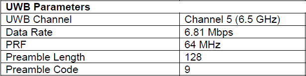
Another question is with regards to the data rate/bandwidth and preamble configuration. I have tried to modify the configurations for a lower bandwidth (enabling a larger range). After playing around with the config parameters and seeing timeout errors I modified the configuration to:

static dwt_config_t config = {
  5,                /* Channel number. */
  DWT_PRF_64M,      /* Pulse repetition frequency. */
  DWT_PLEN_4096,     /* Preamble length. Used in TX only. */
  DWT_PAC64,         /* Preamble acquisition chunk size. Used in RX only. */
  9,               /* TX preamble code. Used in TX only. */
  9,               /* RX preamble code. Used in RX only. */
  0,                /* 0 to use standard SFD, 1 to use non-standard SFD. */
  DWT_BR_110K,       /* Data rate. */
  DWT_PHRMODE_STD,  /* PHY header mode. */
  (4096 + 1 + 64 - 64)     /* SFD timeout (preamble length + 1 + SFD length - PAC size). Used in RX only. */
};

This configuration is however not working with the ss_twr_init and ss_twr_resp examples out of the box. In ss_twr_resp the delayed response is not triggered due to an incorrect delay setting. I was surprised to see that I had to increase the delay, POLL_RX_TO_RESP_TX_DLY_UUS, all the way up to 7000 microseconds to make it work.
Why does the data rate and/or preamble length affect the delay configuration of delayed transmissions?

Finally I would like to ask if there are any performance differences between the “plain” examples without PANS compared to the PANS example?
Should I expect a better range accuracy and performance with PANS? Or should I be able to achieve the same, although in a less straight forward (out-of-the-box) way with the plain library?

Looking forward to your response.

Best regards
Thomas Jespersen

1 Like

Hey there,
Thanks for your post because I have some questions like yours too.
I’m gona describe what i know cause i acquire the same mdek as you.
So first, i felt the same way about building my own firmware, cause i dont know what is going on inside de “black box” and cant count with only that to make statistics approaches.
So i build my owm firmware too.
In some post I read that the Mdek uses the 1024 preamble, channel 5 (and the hardware is adapted to that) and 64MHz. On the data rate i think you can choose. Dont remember well.
The examples you see, dwm1000-simple and so on, i think it belongs on past versions, where you have dip switch on hardware to choose the parameters to use - i belive TREK or something uses channel 2, sorry dont remember well.
So, i did the same as you building the firmware using the OTP values (antenna delay, crystal trim, smart tx) on each device. I think all the values (OTP) are right in case of calibration. I notice that the smart tx for 64 and 16 MHz are the same and i only have for channel 5. The rest of OTP slot have 0xfffffff values, so belive were not stored.

What i notice is that the error i got it is similar to yours but changing devices (making my tag to “talk” to another anchor) the error sometimes are less or even a litle bit more. So i think that is because of the antenna delay (mostly)! What i mean is, thoose devices are calibrated with a positive error from factory. I even read in another post that they come from factory with 17 cm mean error and 2 or 3 cm of std error. Another thing could be the bias range. So what it is need to do is calibrate them on a distance, correct the antenna delay value and then try to see the bias correction. - what i did.

In cases of LOS is a good way to get some good result, but when NLOS happen it will have more impact. An error (25 cm) can “help” in a NLOS case.

About the delays you are describing I use a excel sheet (belongs to Decawave) to determine duration of time on communications and general rule, less delay time better. Not a good help i know :(.

About the different configurations you are trying there are a lot of registers that need to be checked and maybe is that the reason of not working. In my case use the decawave documentation user manual to check that the registers… :frowning: painfull but yeah… A quick note, check the delay you use for that configuration. Can be a good reason to not catch comunications between devices.

Sorry the long post.

Hope i could help,
Cheers.

Is anyone from Decawave able to step in and address these questions?
I thought I had made quite an elaborate list of justified questions.

Regards Thomas

Still nobody from Decawave watching this forum?

Greetings all,

I think, Mr. Thomas’s questions are valuable and should be appreciated by any useful answer. Therefore, I wanted to update the post.

Hi,

Thanks for the questions and sorry for the delay.

  1. What is the network configuration used by PANS and compatible with the factory antenna calibration stored in the OTP? Is it the one shown in Table 1 of the DWM1001 System Overview document?
    Yes it is. Listed below.
    image

  2. This gave me the following value: 0x404C404C
    Is the factory calibrated antenna delay equal for both TX and RX? And in this case it seems to also be equal in PRF 64 and PRF 16 mode? ?
    The module is tested with MDEK factor software and is implanted with single-sided TWR algorithm. The TX and RX delay portion in such algorithm is the same. Thus, the calibrated delay is evenly divided into TX and RX with the same value.
    As listed in the answer to Question 1, the embedded software only uses PRF 64. Thus the PRF16 config options are not considered. i.e. the antenna delay of PRF16 is not calibrated. There are still space in the OTP to be used for PRF16. So, if necessary, the DWM1001 module can be further calibrated for PRF16 by the customer.

  3. Why am I observing a 25-30 cm distance bias/error when the factory calibrated antenna delay is used? This appears independent of whether the TX/RX preamble code is set to 10 or 9 (see other question below).
    There can be various reasons. You may need to check (but not limited to) reasons below:

    • whether both devices in your ranging are calibrated;
    • whether range bias is applied;
    • whether the response time is too long.
  4. a. Why is Channel 5 being used in the DWM1001 examples while Channel 2 is used in the DWS1000 examples? This does however align with Table 1 (as mentioned above).
    The DW1000 chip itself is supports various configurations, including different channels (1,2,3,4,5,7). The DWS1000 has DWM1000 module on it. Similar to EVK1000, DWS1000 supports all channels that DW1000 does. The examples aims to show how to perform each individual functions that the chip is capable of. It can choose any channel, with any configuration that works.
    MDEK1001 (DWM1001) is a product with software and is targeting specific use case with specific configurations. It has antenna specifically designed for channel 5. All tests around the DWM1001 module are based on the configuratiosn listed in the answer of Question 1. using other configurations can lead to unexpected performance.

    b. Why is the TX/RX preamble code 10 used in the DWM1001 examples instead of 9 which used in the DWS1000? In this case Table 1 (as mentioned above) defines it to be 9!
    see answer to 4.a

    c. Why is the RX timeout set to the maximum (65 ms) instead of an actual/expected microsecond-ranged value?
    Yes you are right. The 65 ms timeout in the example is too long and is not necessary. Please tailor the timeout values according to the actual/expected values in your design.

    d. Why is POLL_TX_TO_RESP_RX_DLY_UUS set to 100 us in the DWM1001 example and to 140 us in the DWS1000 example? In general, why is this value set so low, given that POLL_RX_TO_RESP_TX_DLY_UUS is already larger than this (330 us in DWS1000 example, 1100 us in DWM1001 example)? Shouldn’t this delay of the response (in the responder) be accounted for in the transmitter? Or at the very least be accounted for in RESP_RX_TIMEOUT_UUS which in the DWS1000 example is only 210 us?
    The POLL_RX_TO_RESP_TX_DLY_UUS indicates the time interval between POLL RX Timestamp (RMARKER) and the RESP TX timestamp (RMARKER). The length of the timings should follow the below:
    POLL_TX_TO_RESP_RX_DLY_UUS + Preamble_length + SFD + PHR + Payload_length < POLL_RX_TO_RESP_TX_DLY_UUS
    In the DWS1000 example, there is:
    POLL_TX_TO_RESP_RX_DLY_UUS + 128 + 8 + 21 + 15 < POLL_RX_TO_RESP_TX_DLY_UUS
    Here the POLL_TX_TO_RESP_RX_DLY_UUS = 100 is almost optimized.
    In the DWM1001 example, the timings can be improved for better performance.
    e. Why don’t you have any responder example with interrupt? I would expect the responder to be the most time-critical application given that the response transmission timestamp is based on the receive timestamp.
    The simple examples only aim to show the very basic implementations of each individual features. They are kept as simple as possible for easy understanding. You can implement interrupt in your own design.

    f. Why is the bias correction, dwt_getrangebias, not applied in any of the examples?
    There is no simple example of the usage of this function. There is usage of it in https://www.decawave.com/wp-content/uploads/2018/09/evk1000_software_package_v1.1.zip
    evk1000_software_package_v1.1\DecaRanging_App_3.05\Source Code\DecaRangingCustomerMP_source_code_rev3p05_vcxproj\application\instance_log.c
    Line 174
    In short, when using it, you do:
    distance = raw_distance - dwt_getrangebias(ch, raw_distance, prf);

  5. So why the heck is UUS_TO_DWT_TIME set to 65536?
    As was mentioned in the code comment, uus indicates UWB microsecond, not microsecond. In calculation, 1 uus is around 1.025 us.

  6. Why does the data rate and/or preamble length affect the delay configuration of delayed transmissions?
    As was mentioned in answer 4.d, the value of POLL_RX_TO_RESP_TX_DLY_UUS should consider preamble_length and payload_length too. In your configuration here, the data package is quite long. Taking 20 bytes payload as example, there is preamble_length ~ 4096us, PHR ~ 172us and payload_length ~ 1707us.
    Please refer to IEEE Std 802.15.4™-2015, section 16. HRP UWB PHY for detailed calculation of each field in the data frame.

  7. Should I expect a better range accuracy and performance with PANS? Or should I be able to achieve the same, although in a less straight forward (out-of-the-box) way with the plain library?
    The PANS system have taken the calibration info, the range bias and some power compensation factors into the operations. I’d expect similar perfromance if your software design based on “plain examples” have all these factors included too.

Best Regards,
Weibo

6 Likes

Hi @Weibo_Pan,

thanks for your detailed answer. Regarding answer 2: Why is the PRF affecting the antenna delay? and why has the channel selection impact on the antenna calibration? Is this answered by “unexpecting performance” because of other configuration then the default one?

Best regards,
Miro