Lets say that we have a symbol. How to see the implementation of that symbol?
To show what I want to ask, lets take a symbol created by Kelvin as example (its easy the implementation of this symbol, but this only to better understand my question, the symbol has no relevance now). Difference.qsym (620 Bytes)
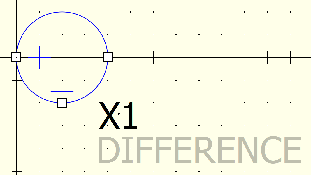
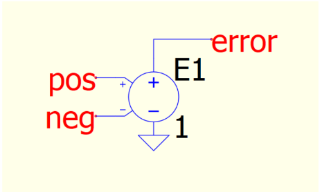
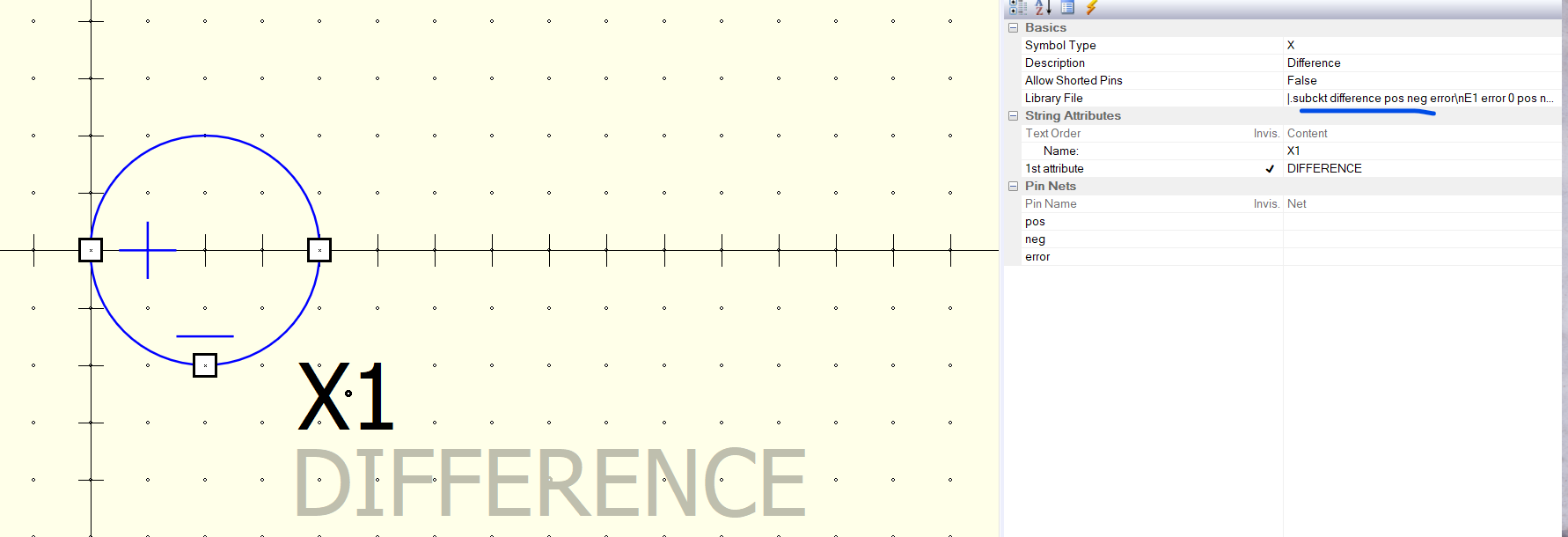
If we open this schematic we will see only the symbol below:
In this case Kelvin showed the implementation in his documentation, but I am wondering in the case where the implementation is not shown how to see the implementation of the symbol
Symbol does not come with the above schematic description (only if it is described somewhere this schematic description of the symbol) when we download the symbol and use it…
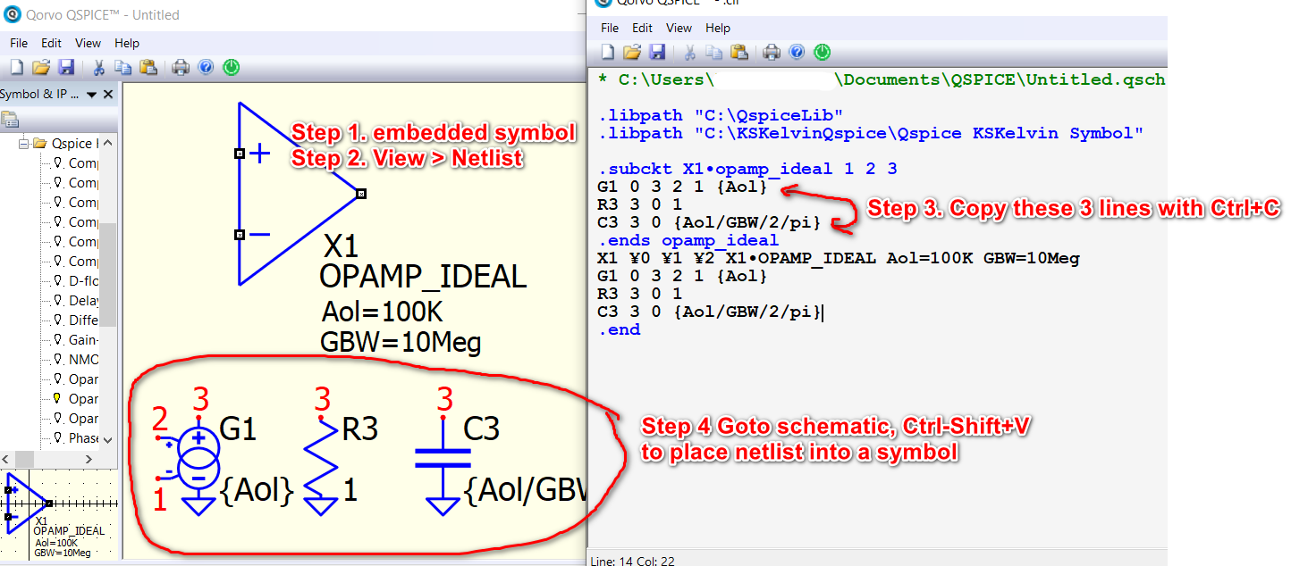
There is no way you can directly get an embedded symbol (one line netlist) or .subckt into a schematic directly. You always have to do it by yourself by drawing schematic from a netlist.
In Qspice, if you copy a netlist, you can use Copy+Shift V to place into schematic with symbol. But for a netlist with multiple devices, you still have to manually rotate devices, reconnect their wire to be a visually readable schematic.
I know this. The question was what to do in the case where another guy (unknow to you) made a symbol and he posted somewhere that symbol. You find that symbol and want to use it (and in fact you can use that symbol without knowing its implementation), but from where you took the symbol there was no any additional details attached to the symbol on what embedded components use that symbol prior to the effective creation of the symbol with lines and circles. And maybe you want to know how that symbol was implemented (what embedded components are enclosed behind that symbol) to know better the symbol that you will use. Your procedure seems to show how to do.
It depends if symbol (i.e. the .subckt) is encrypted or not. If .subckt not encrypt, you should always review the .subckt if you want to study how he design that. All symbol is from .subckt or .model. But I am not sure if I understand your question.
Do you have an example of what you have on hand and what you want to achieve?
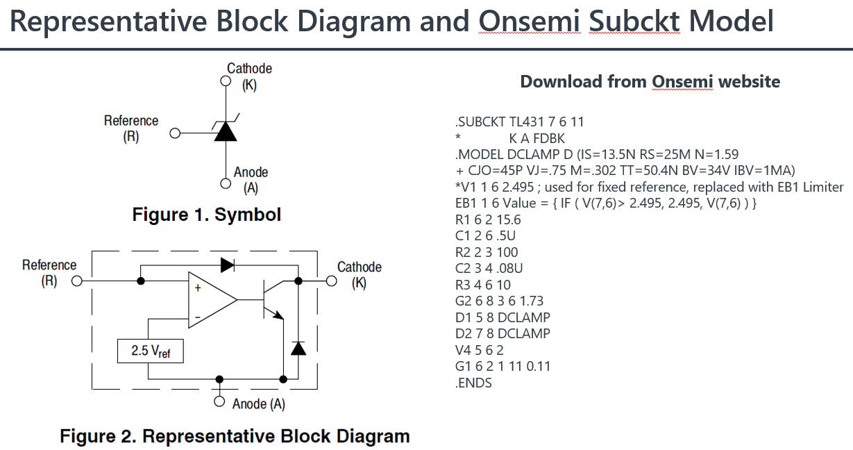
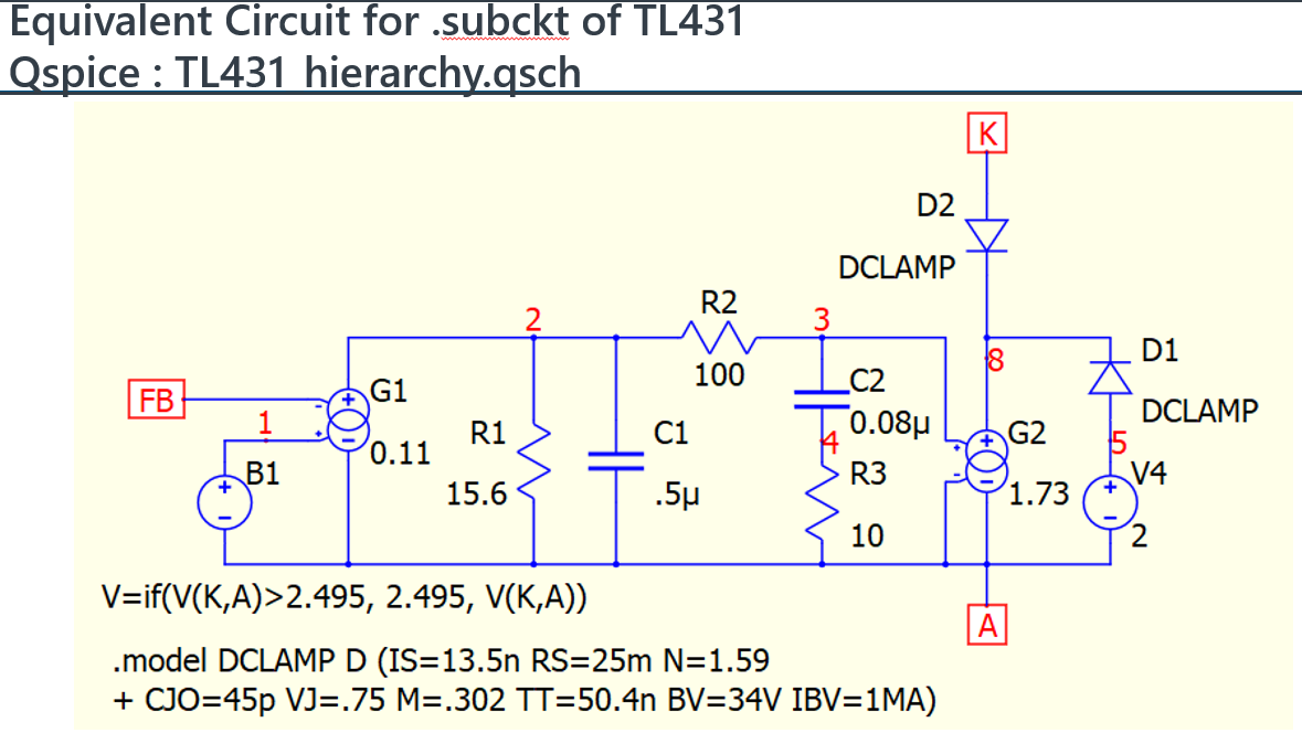
Just like this example. This is a .subckt of TL431 from onsemi, which can be imported to spice for simulation. If you really want to know how this model work, normally we will convert it to a schematic (easier to understand) [2nd picture is my schematic conversion based on .subckt netlist). But can you understand why manufacturer build the model of TL431 in this way, it rely on your electronic and modeling knowledge.
But I have a feeling your question is something else as it seems that you are not asking this.
But you converted this .subckt like you showed in the about quick procedure (with copy and paste like method) where the elements are placed automatically and the label (1, 2, 3) are placed also automatically? Or by understanding spice syntax and making a schematic from your understanding of that spice syntax and without using the above procedure?
Your answer is on what I asked. It’s ok. Your procedure it’s more like a semi-automatic restoring the components which are embedded into the respective symbol by copy the lines which are inside the subckt and then drawing wire manually, thus redoing the unknow implementation of the symbol. I was looking for an automatic way of obtaining the entire schematic with embedded components and wired already made without needed to look into the .subckt implementation and understand what to copy in order to avoid the mistake when copying or when not knowing what to copy from that subckt or if you do not copied all the necessary lines in order to restore correctly the embedded components which are behind the symbol, but knowing what you showed with quick procedure it’s very good to know and answered to my question so far.
@KSKelvin This above showed procedure is very useful and helpful indeed (like a lot, it saves and will save many mistakes), but I think only in QSPICE is this procedure available and can this be done, right? I I did not see that such a procedure is available in LTspice for example.
I cannot recall a copy netlist and paste into symbol method in LTspice. But recently LTspice has a major revision change and I saw it changed some shortcut key similar to Qspice, so, not sure if something new is going on. Anyway, converting a netlist to schematic always a tedious process.
test.qsch (3.9 KB)
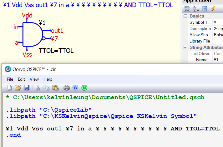
For the above schematic I generated a parent schematic.
Then View->Netlist:
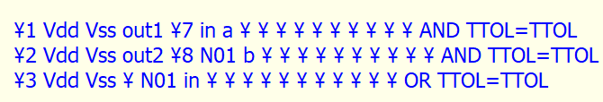
.subckt test in Vdd out1 out2 Vss a b
¥1 Vdd Vss out1 ¥7 in a ¥ ¥ ¥ ¥ ¥ ¥ ¥ ¥ ¥ ¥ AND TTOL=TTOL
¥2 Vdd Vss out2 ¥8 N01 b ¥ ¥ ¥ ¥ ¥ ¥ ¥ ¥ ¥ ¥ AND TTOL=TTOL
¥3 Vdd Vss ¥ N01 in ¥ ¥ ¥ ¥ ¥ ¥ ¥ ¥ ¥ ¥ ¥ OR TTOL=TTOL
.ends test
And for above netlist I created a symbol: test.qsym (824 Bytes)
All was fine.
But if you want to go back and see the above schematic by Copy+Shift V the three lines above, nothing happened - I mean only text I am able to see. Why this is happening?
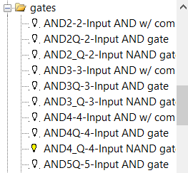
Possibly Mike didn’t implement Ctrl+Shift V for ¥-device. I am not sure this is on purpose of not, as the challenge of ¥-device is its possible variation. For example, there are different AND gates symbol. Currently, I have to do it manually if I need to convert netlist to symbol for special device.
What do you mean by convert manually netlist to symbol?
You mean that someone needs to understand for example this syntax:
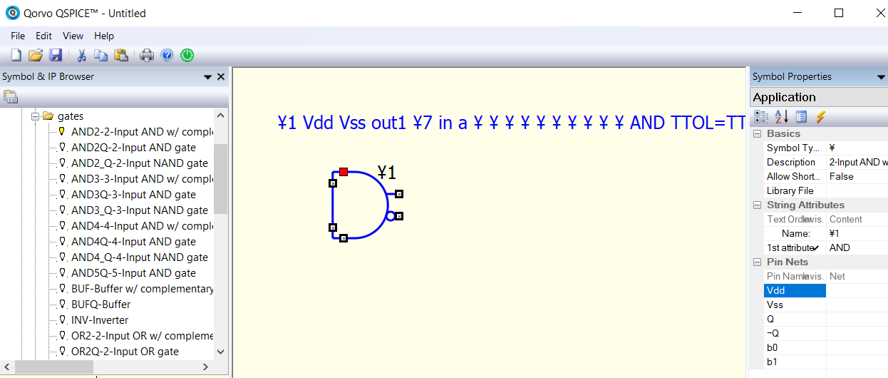
¥1 Vdd Vss out1 ¥7 in a ¥ ¥ ¥ ¥ ¥ ¥ ¥ ¥ ¥ ¥ AND TTOL=TTOL
And to know what symbol/component represent this and also to know what pins are connected where?
From ¥1 syntax, AND is the ¥-device type, and this is AND gate by referring to Qspice HELP with syntax : Syntax: ¥nnn VDD VSS Q Q̅ A B C D E ¥ ¥ ¥ ¥ ¥ ¥ ¥ AND [INSTANCE PARAMETERS]
From ¥1, 6 pins are used, i.e. from VDD to B. In this case, you know you can use 2-Input AND w/ complementary outputs as its symbol. (You can use 3-Input too, but unused pin have to assign to ¥)
Right click device, Show Symbol Properties, and if you select Pin Name (it sequence is always same as netlist sequence), you can know which pin is Vdd, Vss, Q … for example, in this picture, I select “Vdd” and that pin is highlight in RED.
Now, you can manually assign net to this device. TTOL=TTOL is an attribute in this case.
I normally use View > Netlist to make sure I assigned net to pin correctly.
So, basically, you have to get yourself more familiar text syntax of spice to work on this kind of conversion.