Hello
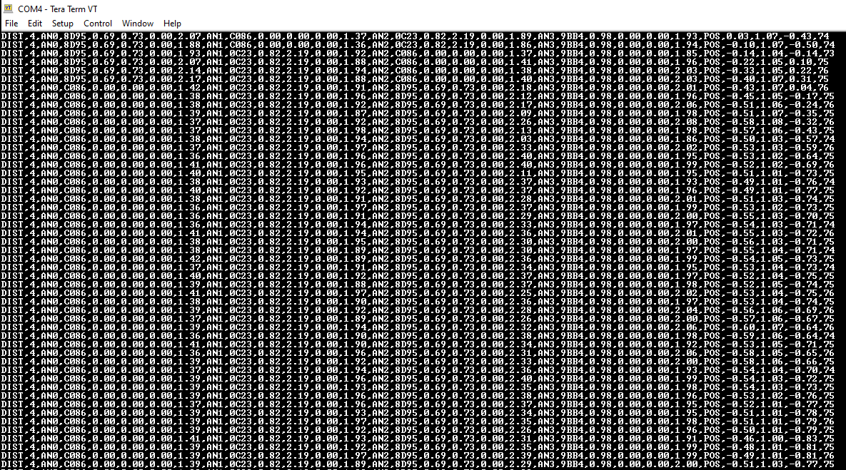
Here is the position obtained but the tag is stationary, why distance and position keep changing while I placed anchor and tag stationary?.
1 Like
Hello
I have a project of estimate the position of the tag by using four anchors on the ground
I configured 4 anchors on the ground and one tag. I tried to do ranging calibration using one anchor and one tag then using LEC command to display distance between tag and anchor. When I placed tag and anchor at 50cm, by using LEC command it gives continuous output and the value is quite bit far from true distance measured using Tape measure
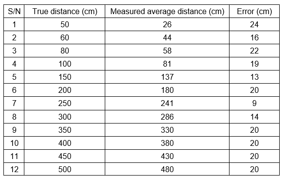
So I collected that changing distance data then find average then note as average distance. What can I do to reduce error to go below 10cm as said in Decawave guide book.
Literally “on the ground”? UWB signals don’t do well when traveling right over a ground plane, it affects the speed of propagation. We find that 15 cm separation from the ground plane (be it actual ground or metal lath such as suspended ceiling grids) is required to mostly negate this behavior.
The visualization I give people is to imagine the UWB signal between two nodes as a super elongated rugby ball with the tip of the ball at each antenna and the ball’s diameter about 30 cm. If the volume of that rugby ball is clear, you have good line of sight. If that volume is partially obstructed, say a steel stud in a wall, it can still work with a bit of signal loss. If you block the cross section of the rugby ball anywhere along the path completely, you won’t get good readings. Thus it becomes more critical at each end near the antennas, and somewhat less critical in the middle of the path. This mental image can help you “see” the UWB signal is space and understand how it is being affected.
This app note discusses in detail the factors that affect error in ranging:
From your data, is seems clear there is at least an antenna delay error. Given your are under reporting the distance, the antenna delay is too large and should be reduced. 20 cm would seems about right (about 43 “ticks” for one side, 22 “ticks” to adjust both sides).
That will make your error pretty small overall. The only reading that is outside the 10 cm error band is 250 cm, and that would only be 11 cm out. I suspect that the 250 cm reading is partly due to your operating situation and may be caused by some reflection in your environment, say off the ground, causing a phase shift in the antenna reception.
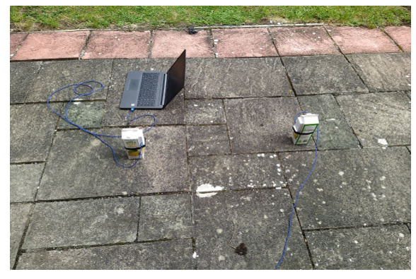
Try this experiment: repeat the above measurements but change the altitude of the devices above the ground, say to 2+ meters. I think you will see there are environmental effects based on the possible bounce of the signal off the ground or other objects.
Finally, if the data is repeatable, then you can develop a calibration table to convert the measured value to the actual value over the region of interest. This corrects for all sorts of things such as antenna group delay, ground bounce, etc.
Mike Ciholas, President, Ciholas, Inc
3700 Bell Road, Newburgh, IN 47630 USA
mikec@ciholas.com
+1 812 962 9408
1 Like
Thank you very much and be blessed Mr. Ciholas
I will put two sensors at height of 2m as your suggestion and observe the error. Below is where experiment was performed, thank you and will improve that. If I put anchor at certain height so I need to manually its height in DRTLS app?
From your data, is seems clear there is at least an antenna delay error. Given your are under reporting the distance, the antenna delay is too large and should be reduced. 20 cm would seems about right (about 43 “ticks” for one side, 22 “ticks” to adjust both sides)
With that statement above so I should not faced each other anchor and tag? or How can I reduced antenna delay error?
How can I reduced antenna delay error?
By setting the antenna delay correctly.
One of the corrections that the DW1000 makes is to compensate for the delay added by the antenna and related PCB connections. You are probably currently using the default values which will be based on the typical values seen in that module design. However every unit is different and so to get good accuracies you need to measure the delay for each unit and set this correction the the correct value. In this case it looks like your units have a slightly lower than typical delay resulting in the measurements being over corrected and reading too short.
If you only have two units then all you can measure is the total error for both of them combined, you can either compensate for this by assigning it all to one unit or splitting it evenly between the two. The end result is the same either way.
With 3 or more units it’s possible to calculate the delay for each unit independently, a more complicated but more desirable solution to the problem. There is an app note on this subject.
Once you know the correct correction to make the firmware should provide a means of setting the required value in each unit.
Thank you very much for your explanation, How can I measure delay bcoz using Teraterm I can only measure distance and position and that antenna delay how can I set to get accuracy value?
In DRTLS app, I cant see that setting.
The antenna delay is calibrated at the factory for the DWM1001C per section 2.1.3 of the DWM1001C datasheet. I believe his photo shows an MDEK, which has a DWM1001C inside it.
The firmware needs to make use of this calibration value for it to have any effect, of course, and maybe that isn’t happening.
It is also possible that the calibration value is being used, but other effects, like being near the ground, or the particular antenna rotation, or what is near the antenna, could shift the antenna delay.
Another test I suggest is to rotate the units slightly. Disturbances in the group delay of antennas tend to be worse on the cardinal axis (0, 90, 180, 270 degrees) so try 30 or 45 degrees off and see what happens. It is not uncommon to get 5 to 10 cm of range change with rotation especially for small module sized antennas. In our lab, we’ve spent a lot of time developing antennas which have minimal range error with rotation.
Here is a link to that app note so you can find it easily
Mike Ciholas, President, Ciholas, Inc
3700 Bell Road, Newburgh, IN 47630 USA
mikec@ciholas.com
+1 812 962 9408
Thank you very much for your good explanation. Be blessed Eng, Ciholas. Let me follow your instruction.
So good test is to not face each other that sensors. So one sensor face should be point one direction and another should point slightly at small angle from first point direction.
You can rotate the sensors and check what that does for the range accuracy. You need to know where the module antenna is so that you rotate about its axis.
We built an antenna positioner device so we can do automated tests at various azimuths and elevations. Here is a pattern scan:

This helps us develop antennas with minimal range variation in their pattern.
Mike Ciholas, President, Ciholas, Inc
3700 Bell Road, Newburgh, IN 47630 USA
mikec@ciholas.com
+1 812 962 9408
1 Like
Thank you very much for the demo Eng. Ciholas. You are great
Hi Kivule, members,
Have you fixed this error?
I have seen the antenna distance calibration document is not downloading from the website.
Any help would be great!
Thanks in Advance!
Satya